 Inventing Circuits on the Whiteboard...
How do We Create a Virtual Ground?
Is there simpler and, at the same time, so mysterious circuit phenomenon as virtual ground? I think, there is not...
How many time I have been asking myself, "What is actually a virtual ground?", "What does it mean?", "How can we create it?", "What is the difference between a virtual and a real ground?", "Is a virtual ground useful or harmful phenomenon?, "Is it possible to connect a virtual with a real ground?", etc. Finally, I have managed to answer these questions...
As usual, in this exciting story we will look here for answers not only in the electricity (electronics); instead, we will first try to find remedies (mechanical, fluid, thermal, social, etc.) in our human routine. In order to "feel" the phenomenon, we will tow ropes playing at tug of war and arm wrestling, pump up and out an air, fill up and drain reservoirs etc.
Finally, we will convince ourselves that there is nothing special in the virtual ground phenomenon; imagine it is nothing else than just to create and keep up a steady voltage (usually zero volts)! According to this viewpoint, we may think of a circuit with virtual ground point as a constant voltage source, where the virtual ground point serves as a source output. Do you agree with this assertion? Well, let's examine it!
Internal links:
1. Non-electrical domain: The "neutralizing" idea
2. Electrical domain: Parallel summing of opposite voltages
3. Keeping up a steady virtual ground by using a dynamic resistance,
4. ...by using a negative resistance,
5. ...by applying a negative feedback.
6. Comparison between real and virtual power ground
8. Virtual ground serving as a circuit point: an input,
9. ...an internal point,
10. ...an output.
Color key
Links: this page, other my pages, external, multimedia, handmade.
Text: analogies, conclusions.
top < prev step - 1 - 2 - 3 - 4 - 5 - 6 - 7 - 8 - 9 - 10 - next step > end
Non-electrical domain : The "neutralizing" idea
Virtual ground is not only a "mystic" electronics phenomenon that we can observe only in op-amp circuits with parallel negative feedback (op-amp inverting circuits). It is a unique worldly phenomenon that we can observe in many situations of our human routine where we solve problems in a wasteful and extravagant way - by continuous wasting of additional energy. Here are a few funny examples revealing the philosophy behind this great idea.
We may observe the virtual ground phenomenon in many situations of our routine when we - especially being lazy and, at the same time, rich enough:) - solve the problems by continuous wasting of additional energy. Examples:
Thermal. Assume you keep the temperature in your room at 20° C (this is your thermal virtual ground). Now imagine that you have broken a window; as a result, the temperature in the room begins dropping (if it is winter) or rising (if it is summer). What do you do?
Obviously, you have to repair the broken window. But if you are too lazy and, at the same time, rich enough:), there is another strange solution to retain the desired temperature. You can turn on a heater (in winter) or an air-conditioner (in summer) and adjust them so that to compensate completely the thermal losses caused by the broken window and to restore the thermal virtual ground.
Hydraulic. Water begins pouring through a hole into the ship's hold because of wreck. In order to keep the desired water level (height virtual ground) the sailors begin continuously pumping out the water instead to plug up the opening. An opposite "hydraulic" example: water begins outflowing from a reservoir because of punching. In order to keep the water level they begin continuously filling the reservoir with water instead to plug up the opening.
Pneumatic. Air flows out the tire since it is punctured. In order to keep the desired air pressure (pressure virtual ground) the driver begins pumping up the tire instead to repair it (in motorized forces, they do that in motion). Another "pneumatic" example: if we pump up a pipe on the one side and pump out it on the other side, a pressure virtual ground appears somewhere along the pipe (we might use an old-fashioned air cleaner, which sucks and blows air through a closed loop made from a corrugated hose for this funny experiment).
Money. I have given another credit card of my account to my wife. Only, she has begun intensely spending my money:((( Trying to keep the desired money virtual ground, I have begun working hard to earn money (instead just to scold my wife). By the way, don't you think that it is interesting the fact that in life whether they work and spend hard or they work and spend little, the result (money virtual ground) is the same:)
Game. In the popular games of arm wrestling and tug of war, a "position" virtual ground appears in the middle when fighting people push and pull with equal power.
Conclusion. If we connect each other two opposite power sources by a conductive medium so that their opposite output quantities are superposed (summed), zero or reference level result (virtual ground) appears somewhere along the medium. In this "conflict" point, the efforts of the "fighting" sources are "neutralized". The process is associated with continuous energy wasting from both the sources as a result of a continuous energy flow through the medium.
Virtual ground phenomenon is summing of opposite equal quantities, which is associated with continuous energy wasting.
Virtual ground point represents the result of summing two opposite and usually equal quantities.
Creating a simple virtual ground
top < prev step - 1 - 2 - 3 - 4 - 5 - 6 - 7 - 8 - 9 - 10 - next step > end
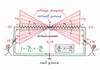
Let's now create an electrical virtual ground. Following the general recipe above, we have to sum two opposite voltages so that a point having zero voltage to appear between the two voltage sources. Only, it is incorrect to connect directly voltage sources in parallel because a conflict will appear between them (in spite of all, they use this technique in common base amplifier, differential amplifiers, etc.) Then, let's connect the two opposite voltage sources (+V1 and -V2) through respective resistors (R1 and R2) to the virtual ground output (the voltage VA between the real and the virtual ground). In this way, the two resistors will "soften" the conflict between the two "fighting" voltage sources.
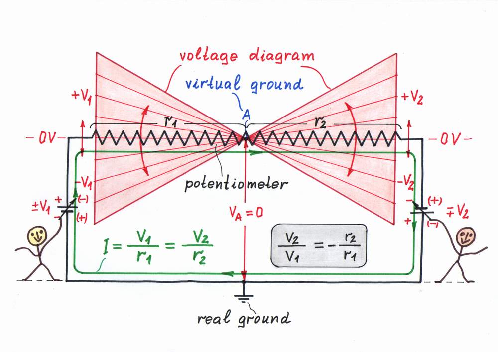
But what is this circuit actually? From one viewpoint, it consists of two parallel connected current sources - I1 (built by V1 and R1) and I2 (built by V2 and R2). From another viewpoint, the two resistors constitute an extremely useful resistive circuit of a parallel voltage summer; we will frequently use it in the circuits with parallel feedback (op-amp inverting amplifier, op-amp inverting summer, op-amp non-inverting Schmitt trigger, etc.)
Electrical domain : Parallel summing of opposite electrical quantities
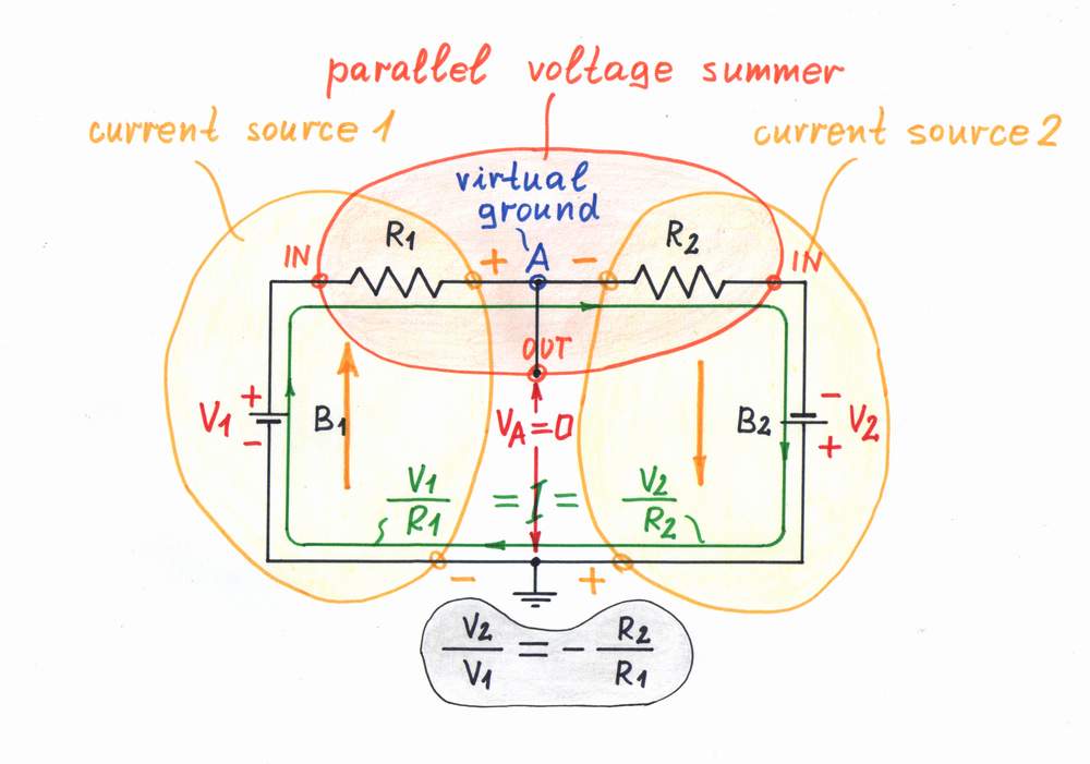
We may think of this resistive circuit as an electrical "tug of war", where two voltage sources "fight" - V1 "pulls" the point A up while V2 "pulls" it down; the pull-up resistor R1 and the pull-down resistor R2 serve as electrical "ropes". If V1/V2 = -R2/R1, zero voltage appears in the point A; it is a virtual ground. In this arrangement, a current I = V1/R1 = V2/R2 passes continuously through the circuit; as a result, the resistors dissipate continuously power.
Virtual ground appears in the common point between two series connected resistors, if
• two voltages are applied to the other ends of the resistors,
• they have opposite polarities,
• they bear the same proportion as between the respective resistors.
V1/V2 = -R2/R1
Virtual ground presented as an electrical "tug of war"
Keeping up a steady virtual ground...
top < prev step - 1 - 2 - 3 - 4 - 5 - 6 - 7 - 8 - 9 - 10 - next step > end
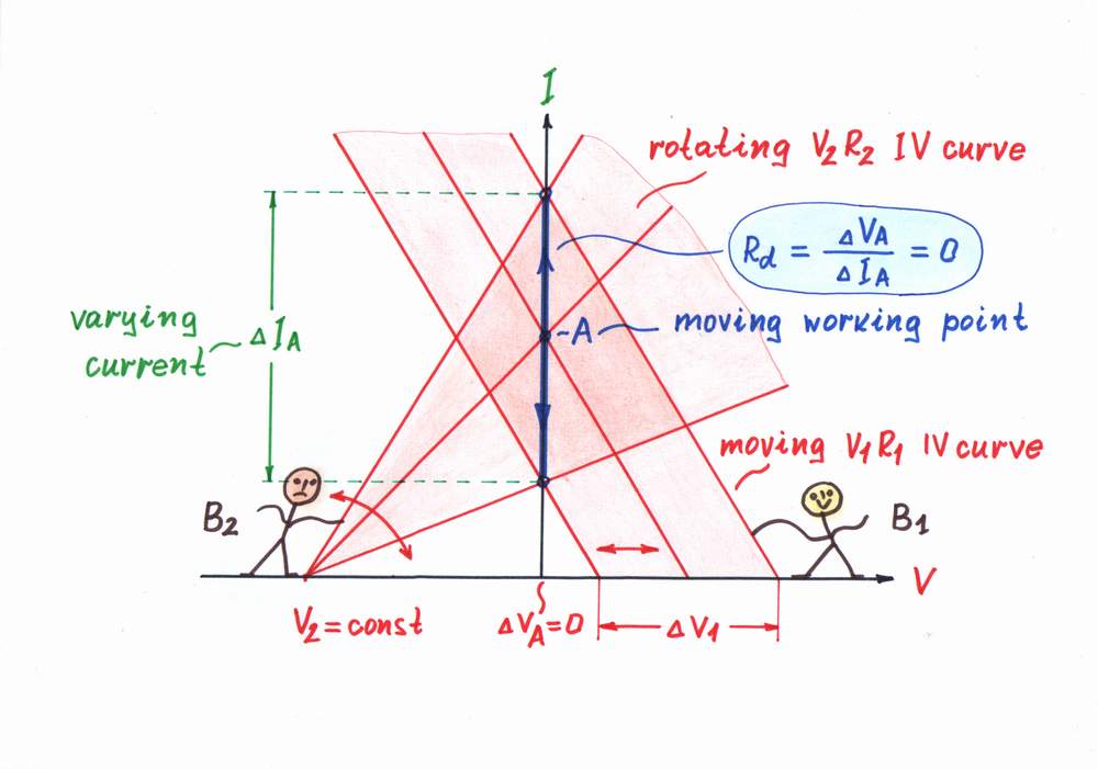
Varying resistance. Once we created a virtual ground, we have to keep it up steady, in order to resist the eventual influences. For this purpose, we may use the well-known dynamizing technique. Following this great idea, we may first keep up the virtual ground by varying the resistance. That means to implement the resistor R2 as a voltage-stable dynamic resistor (diode, zener diode, LED, etc.)
If the voltage V1 rises, the current I increases and the zero voltage VA of the point A (the virtual ground) tries to rise. However, the dynamic resistor R2 decreases its present resistance thus restoring the zero voltage VA and v.v.
On the graphical presentation, when the IV curve of the voltage source B1 moves horizontally from left to right the R2 IV curve rotates contraclockwise. As a result, the working point A slides from bottom to top over a new vertical IV curve, which represents the zero dynamic resistance Rd of the virtual ground.
...by using a dynamic resistance
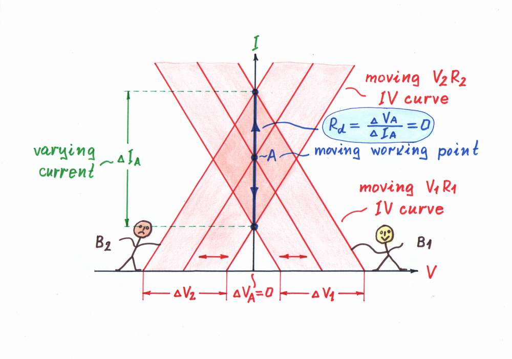
Varying voltage. We know another powerful technique for creating a dynamic resistance - by varying the voltage. Then, let's put this great idea into practice. For this purpose, we have to implement the voltage source B2 as a varying voltage source.
Now, if the voltage source B tries to "pull" the virtual ground A up by raising its voltage V1 towards its positive voltage, the "dynamic" voltage source B2 "pulls" it down by increasing its voltage V2 towards its negative voltage and v.v. As a result, the point A retains its zero voltage.
On the graphical presentation, when the IV curve of the voltage source B1 moves horizontally from left to right, the IV curve of the voltage source B2 moves horizontally from right to left and v.v. As a result, the working point A slides from bottom to top over a new vertical IV curve, which represents the zero dynamic resistance Rd of the virtual ground. We may implement this idea by using a negative resistor or a negative feedback.
top < prev step - 1 - 2 - 3 - 4 - 5 - 6 - 7 - 8 - 9 - 10 - next step > end
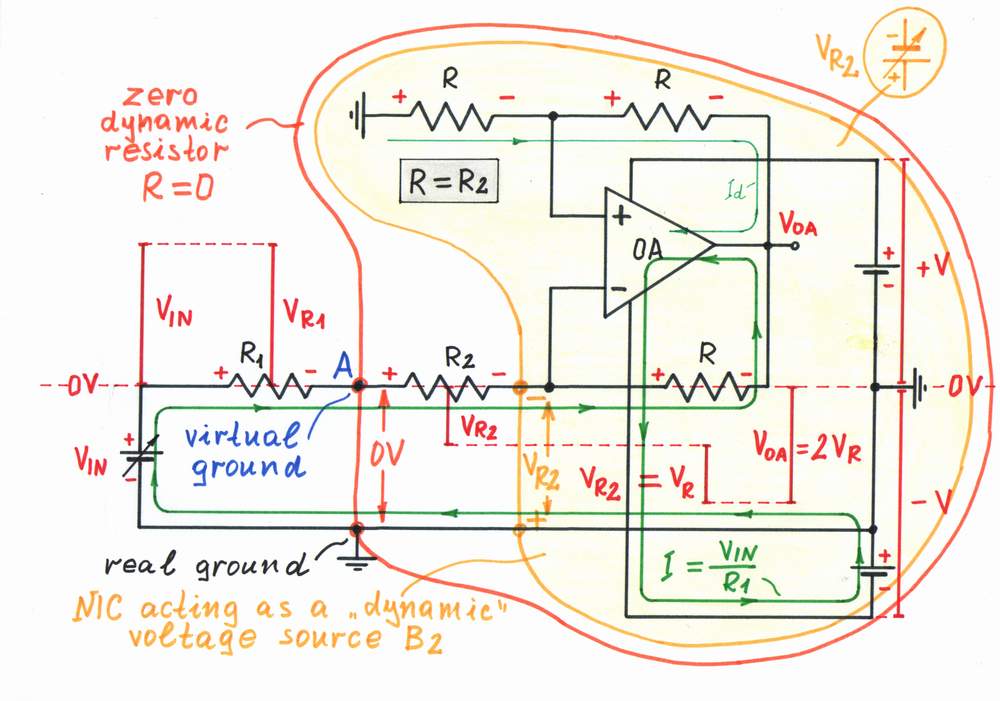
Implementation. For example, let's show how to keep up a steady virtual ground by using an exotic op-amp circuit with negative resistance - a negative impedance converter (NIC). As we know, it has the unique feature to compensate the losses by injecting energy into the circuit. Then, let's replace the steady voltage source B2 with a negative impedance converter acting as a negative resistor with resistance -R. For this purpose, we choose a resistance of the "copy" resistor R inside the NIC (below the op-amp) R = R2.
Operation. The "copy" resistor R converts the flowing current I into proportional "mirror" voltage drop VR = R2.I. The op-amp adjusts 1/2 of its output voltage VOA equal to the "mirror" voltage drop VR = VRi across the "copy" resistor R (the upper two resistors R constitute a voltage divider with ratio 0.5). As a result, the op-amp produces two times higher output voltage VOA = -2VR2. Half the voltage compensates the voltage drop VR = VR2 across the NIC's "copy" resistor; the rest half compensates the voltage drop VR2 across the resistor R2. As a result, a virtual ground appears in the point A between the resistors R1 and R2. Even, if we increase the resistance R, the virtual ground point A will move somewhere inside the resistor R1!
...by using a negative resistance
top < prev step - 1 - 2 - 3 - 4 - 5 - 6 - 7 - 8 - 9 - 10 - next step > end
Of course, the most popular way of keeping some quantity up is a negative feedback. In our case, that means the varying voltage source B2 to "observe" continuously the voltage VA of the virtual ground point and to change its voltage V2 so that the voltage VA stays always zero.
Implementation. An op-amp inverting amplifier is a typical circuit where the virtual ground point is kept up by applying a negative feedback. Let's illustrate more attractively the circuit operation by means of a voltage diagram; for this purpose, let's replace the two resistors by one linear potentiometer.
Operation. If the input voltage source changes its voltage -VIN towards the negative supply voltage -V, a negative voltage VA = -VR2 /(VR1 + VR2) tries to appear in the point A. Only, the op-amp "observes" that and immediately reacts: it changes its output voltage VOA toward the positive supply voltage +V until it manages to zero the potential VA (to restore the virtual ground).
On this graphical presentation, the two sources "pull" the virtual ground point A in different directions; as a result, the voltage diagram rotates around the point A. Actually the op-amp serves here as the varying voltage source B2.
...by applying a negative feedback

Comparison between the two techniques
Maybe, you think that negative feedback is a perfect technique for keeping up a virtual ground as it compensates various disturbances. Only, it can't keep up exactly zero voltage in this point; this voltage is VA = VOA/A (A is the op-amp gain without a negative feedback applied). Typically, A > 100,000 ; so, VA is almost zero.
It looks strange, but we may create and keep up a perfect virtual ground (having exactly VA = 0) without using negative feedback. Only, it will not be as stable as the virtual ground kept by applying a negative feedback.
Finally, don't you think that there is nothing special about the virtual ground phenomenon; it is nothing else than to create and keep up a steady voltage (usually zero volts). According to this viewpoint, a circuit with virtual ground point acts as a constant voltage source, where the virtual ground point serves as a source output.
Applications: Virtual ground serving as a power ground
top < prev step - 1 - 2 - 3 - 4 - 5 - 6 - 7 - 8 - 9 - 10 - next step > end
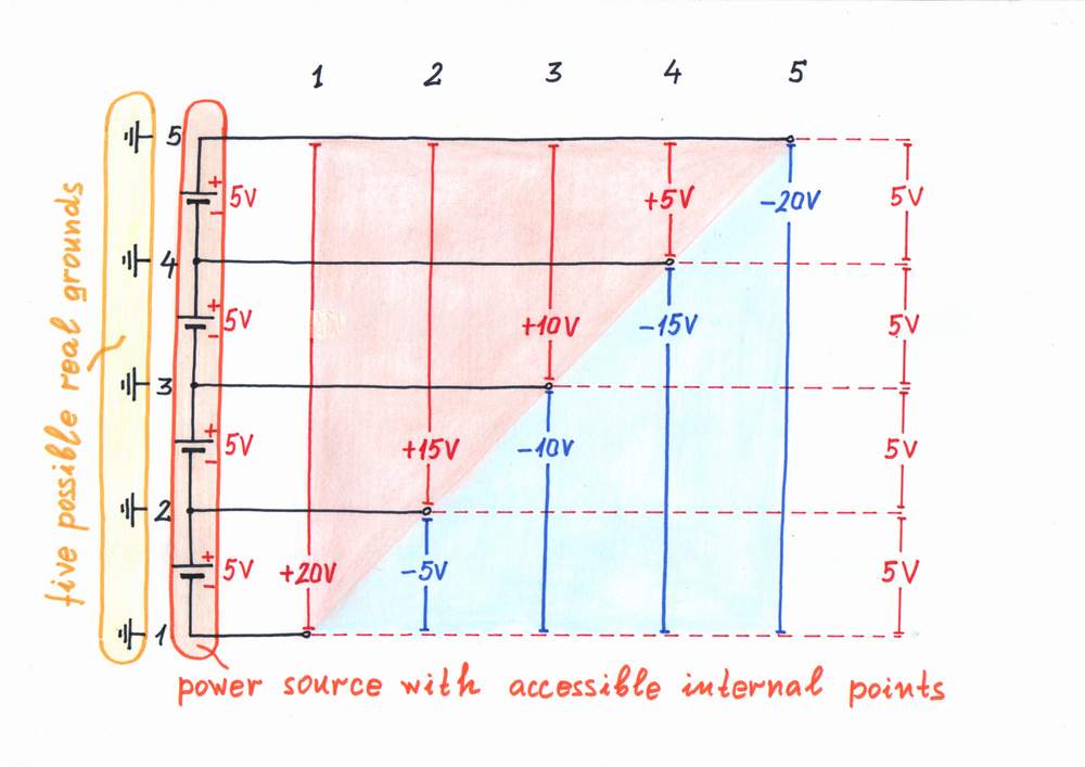
Real power ground. Voltage is a differential quantity, which appears between two points. In order to deal only with a voltage (an electrical potentia) of a single point, we have to connect the second point to a reference point (ground) having usually zero voltage. The ground has to have a steady potential, which does not vary when the electrical sources "attack" the ground by "injecting" or "sucking" a current to/from it. Usually, we use the power supply terminals as grounds; if we can reach the internal points of compound power sources, we may use them as real grounds.
Real ground is a point with a steady voltage inside the supply voltage source.
Comparison between real and virtual power ground
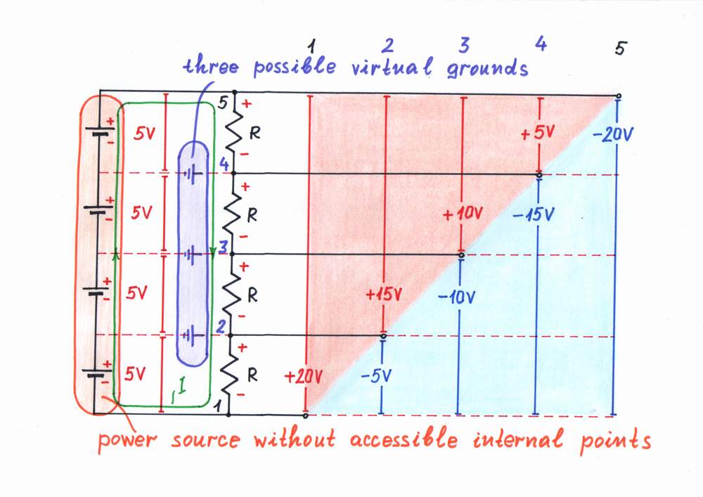
Virtual power ground. If there are not accessible source internal points, external circuit points having steady voltage towards the source terminals can serve as artificial virtual grounds. As usual, we may create such external points by using a resistive voltage divider. Only, what is virtual ground compared with a real ground?
Virtual ground is a circuit point with a steady voltage outside the supply voltage source.
From this viewpoint, there is nothing special about the virtual ground phenomenon; it is nothing else than to create and keep up a steady voltage (usually zero volts).
top < prev step - 1 - 2 - 3 - 4 - 5 - 6 - 7 - 8 - 9 - 10 - next step > end
Some questions appear now: What kind of ground is better? When to use a real ground and when a virtual ground? In order to answer, we have to compare the two grounds regarding the consumption.
Real ground (the right part of the figure). In this most economical case, only the load dissipates a useful power: P1 = I1.V.
Static virtual ground (the left part of the figure). This is the worst case as both the Element 1 and Element 2 dissipate an additional useless power (note, that the current I2 passes through the lower element of this voltage divider because the load is connected to the positive rail):
P2,3 = PL + P'E2 + P"E2 + PE1 = 2I2.V + 2I3.V = 2(PL + PE )
The lower resistive the voltage divider is, the more steady the virtual ground is; only, the consumption increases. In addition, this simple configuration is prone to become unbalanced.
Dynamic virtual ground. In this worse case, only the dynamic Element 2 dissipates a relatively small additional power (usually, the Element 1 does not exist in this arrangement):
P3 = PL + PE2 = 2I2.V = 2PL
Energetical considerations
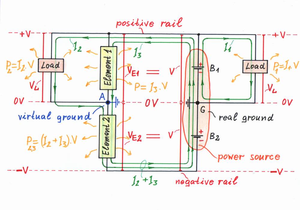
Whenever it is possible, use a real ground to reduce the consumption!
Virtual ground serving as a circuit point:
top < prev step - 1 - 2 - 3 - 4 - 5 - 6 - 7 - 8 - 9 - 10 - next step > end
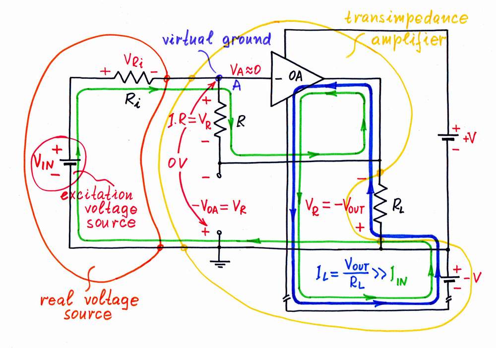
In all the circuits with parallel negative feedback (e.g., the inverting op-amp circuits), the main duty of the (op-amp) amplifier is to "look after" the virtual ground, in order to keep an almost zero voltage at this point. Only, the input sources affect the virtual ground by "injecting" or "sucking" a current to/from this point. In the simplest case, the input current sources do this directly (examples: transimpedance amplifier, current integrator, etc.) For example, the op-amp of a transimpedance amplifier (the figure on the right) tries to change the virtual ground via the resistor R.
The op-amp reacts to the input intervention, in order to restore the normal virtual ground state (VA = 0). For this purpose, it changes its output voltage, in order to "suck" or to "push" a current through a given circuit component (a capacitor, a diode, a resistor, etc.) from/to this point. In this way, the op-amp's output voltage in the circuits with parallel negative feedback represents the op-amp's reaction to the input intervention.
The virtual ground point as an input
top < prev step - 1 - 2 - 3 - 4 - 5 - 6 - 7 - 8 - 9 - 10 - next step > end
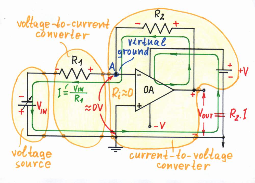
An intervention point. The input voltage sources affect the virtual ground existing in the op-amp circuits with parallel negative feedback through a circuit component acting as a voltage-to-current converter - a resistor (inverting amplifier - see the figure on the right, integrator, logarithmic amplifier), a capacitor (differentiator), a diode (antilogarithmic amplifier), etc. In some circuits (for example, summing amplifier), a few input sources "attack" simultaneously the virtual ground.
As above, the op-amp reacts to the input intervention, in order to restore the normal virtual ground state (VA = 0). For this purpose, it changes its output voltage, in order to "suck" or "push" a current through another circuit component (a capacitor, a diode, a resistor, etc.) from/to this point. Actually, the op-amp's output voltage in the circuits with parallel negative feedback represents the op-amp's reaction to the input intervention.
Although the virtual ground point is the actual output of the circuits with parallel negative feedback, in this case it is non-used. Instead, the op-amp reaction to the input intervention against the virtual ground is used as an output.
The virtual ground point as an internal point
A conflict point. Aslo, we may observe a virtual ground in the common point between the emitters of the two transistors of a transistor differential amplifier at differential input signal. Similarly, a virtual ground appears at the internal middle point of the common resistor connecting the outputs of the input op-amp followers of an instrumentation amplifier working at differential input signal.
Purposely worsened virtual ground. In some single-supplied circuits with positive feedback (for example, an op-amp inverting comparator with hysteresis or Smitt trigger), we worsen preliminarily the virtual ground. In this arrangements, this point has significant internal resistance, in order to be easily influenced by the op-amp output. We frequently use the same trick in the single supply op-amp circuits with negative feedback.
top < prev step - 1 - 2 - 3 - 4 - 5 - 6 - 7 - 8 - 9 - 10 - next step > end
Clipping indicator. In the circuits with parallel negative feedback, the voltage of the virtual ground point indicates the system's state. When the system works properly, its output quantity (usually voltage) manages to "neutralize" the input influence in the virtual ground; there is approximately a zero voltage in this point. If the system runs out of output voltage, it saturates and a voltage appears in the virtual ground (click Exploring button and go to Page 7-1, in order to see an animated presentation of this phenomenon). Actually, this voltage is a part of the input voltage. For example, in the circuit of an inverting amplifier above, the resistors R1 and R2 act as a voltage divider; therefore, R2/(R1 + R2) part of the input voltage begins crossing over to the op-amp's inverting input when the op amp saturates. We may use this voltage (for example, in audio amplifiers) as an output signal indicating the clipping.
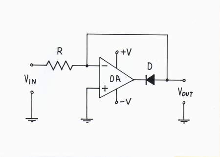
Diode limiter. In some circuits (for example, a parallel diode limiter), the virtual ground point is the output of the circuit.
The virtual ground point as an output
Links to other resources about virtual ground circuits
Reinventing transimpedance amplifier in eight consecutive logically connected steps,
Inverting op-amp current source is based on a virtual ground concept
Reinventing op-amp inverting summer - an animated flash movie revealing the secret of the circuit
Op-amp circuit builder shows how to build various op-amp inverting circuits keeping virtual ground (an animated flash movie)
How I revealed the secret of parallel negative feedback circuits - an exciting story about the phenomenon
Analog electronics 2004: Class 9 - from the exercises with my students
Wikipedia: Virtual ground, Voltage-to-current converter, Current-to-voltage converter, Negative resistance
Other: Virtual Ground Circuits, Single Supply Op Amps, Designing Single Supply, Low-Power Systems
circuit-fantasia > circuit stories > inventing circuits > virtual ground
Last updated December 9, 2007