circuit-fantasia > circuit stories > building circuits > Op-amp inverting RC integrator roll short
Building Circuits on the Whiteboard...
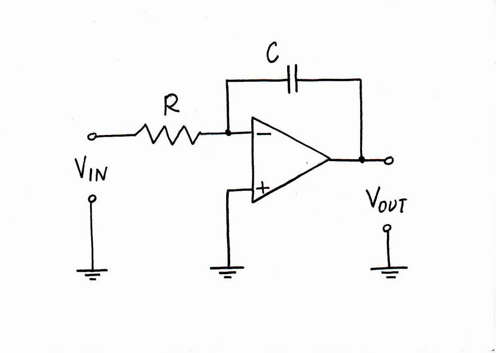
How do We Build an Op-amp RC Integrator?
< prev step - 0 - 1 - 2 - 3 - 4 - 5 - next step >
Classic explanations. As the inverting input of the op-amp is at virtual ground (0 V), the input current is constant and determined only by the input voltage VIN and the resistor R. The output voltage Vout is a copy of the voltage across the capacitor C... See more classic explanations...
Only, what is the basic idea behind this circuit? Let's build it on the whiteboard, in order to reveal the truth...
What is the basic idea behind this circuit?
< prev step - 0 - 1 - 2 - 3 - 4 - 5 - next step >
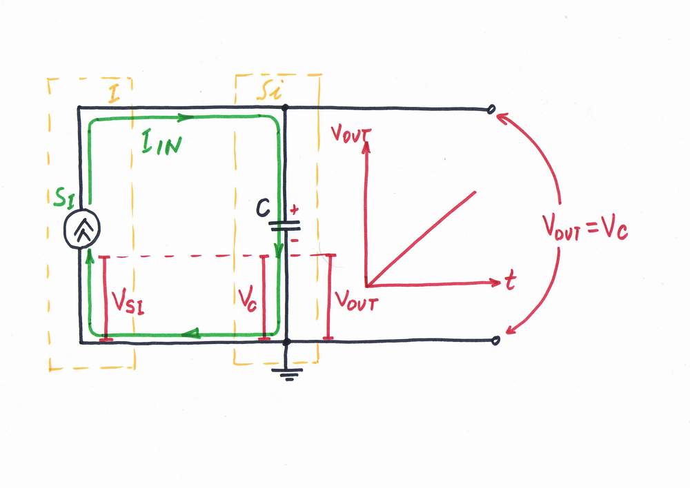
What is the most elementary electrical integrator? Of course, this is capacitor...
If we drive a capacitor C by a constant current source SI, it functions as an ideal current-to-voltage integrator with a current input IIN and a voltage output VOUT = VC. Note that the output voltage changes linearly through the time.
< prev step - 0 - 1 - 2 - 3 - 4 - 5 - next step >
Only, we need usually an integrator with voltage input and voltage output (voltage-to-voltage integrator).
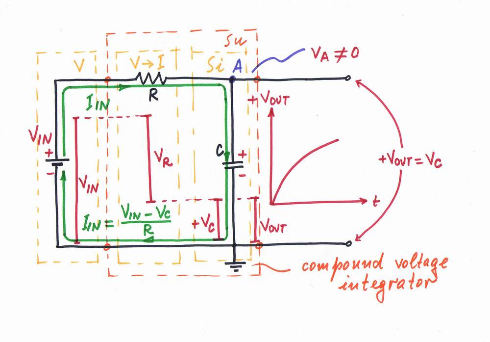
Remedy 1: Let's build a compound voltage integrator just connecting a voltage-to-current converter before the integrator:
V-to-I converter + I-to-V integrator = V-to-V integrator
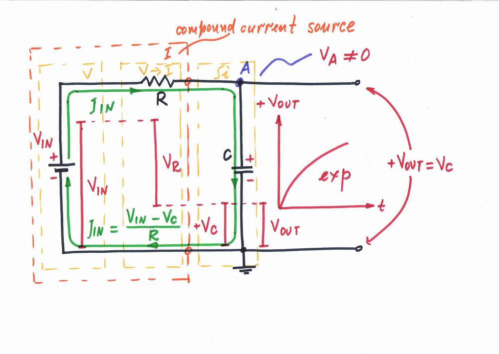
Problem. Only, a problem arises here - the voltage drop VC across the capacitor C "enervates" the input voltage thus decreasing the input current. As a result, the output voltage changes exponentially through the time.
Remedy 2: Remember that we have to pass a constant current through the capacitor; i.e. we have to drive the capacitor by a constant current source. But a suitable current source does not exist in nature; so, we may build it just connecting a voltage-to-current converter after the input voltage source:
V-source + V-to-I converter = I-source
Contradiction. Remembering the problem above, we may note that there is a contradiction here: from one side, the voltage drop VC has to be as small as possible, in order not to disturb the input voltage; from the other side, it has to be as high as possible, in order to give a significant output signal. Then what do we do?
< prev step - 0 - 1 - 2 - 3 - 4 - 5 - next step >
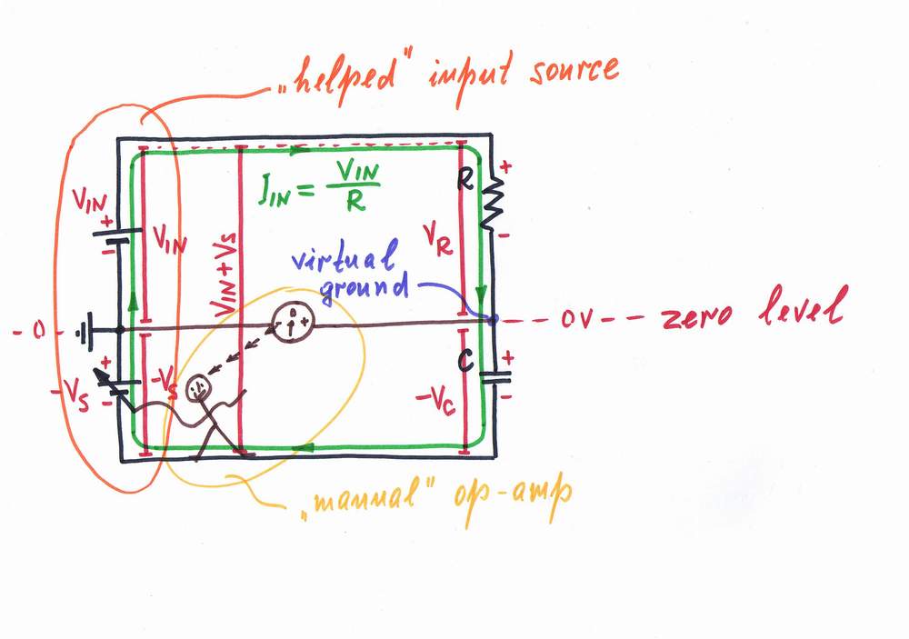
Remedy. What do we do in real life when an obstacle stands in our way? We remove it by an equivalent useful "antidisturbance".
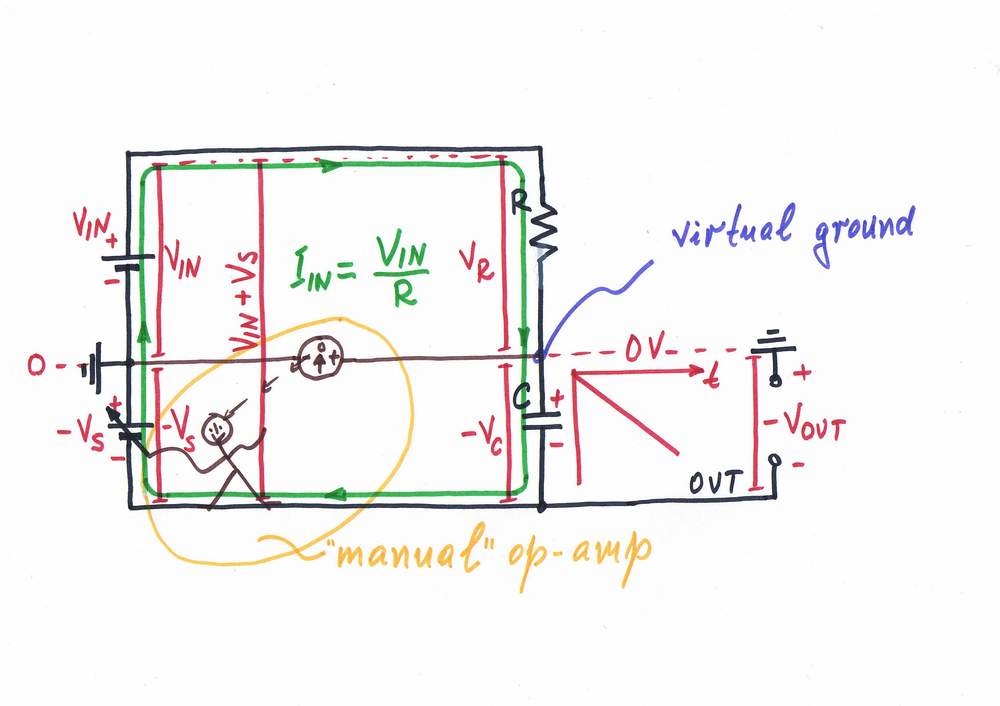
Following this recipe, we may remove the "harmful" voltage VC by an "antivoltage" -VC. That means to connect an additional supplementary battery BS and to adjust its voltage so that VS = -VC. As a result, the "harmful" voltage VC disappears and the point A becomes a virtual ground! The compound current source VIN-R is "fooled": it doesn't "understand" that there is a capacitor connected; it "thinks" that its output is shorted.
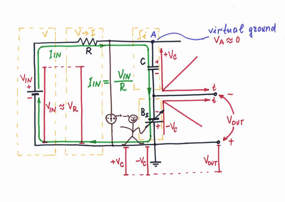
Actually, the additional source helps the input source injecting exactly as much voltage as it drops across the capacitor.
Note that the two voltage sources are connected in series, in one and the same direction (+ -, + -) so that their voltages are added.
< prev step - 0 - 1 - 2 - 3 - 4 - 5 - next step >
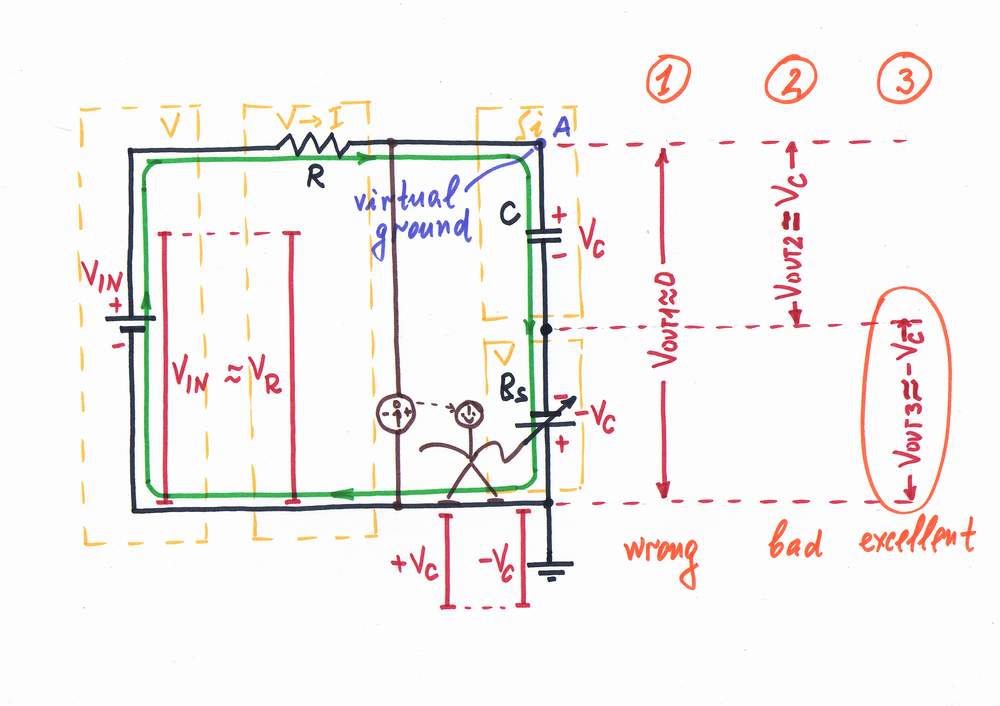
Taking an output. Only, where to take the output? We have three choices:
1. VOUT1 = VA - using the old output. But we have already destroyed this voltage!
2. VOUT2 = VC - using the "original" voltage as an output. It is possible but bad solution to connect the load across the capacitor for two reasons: the load has to have a differential output; the load will shunt the capacitor thus affecting the current.
3. VOUT3 = -VC - using the "copy" voltage as an output. What a great idea! First, the load will be connected to the common ground; second, it will consume energy from the supplementary source BS instead from the input one!
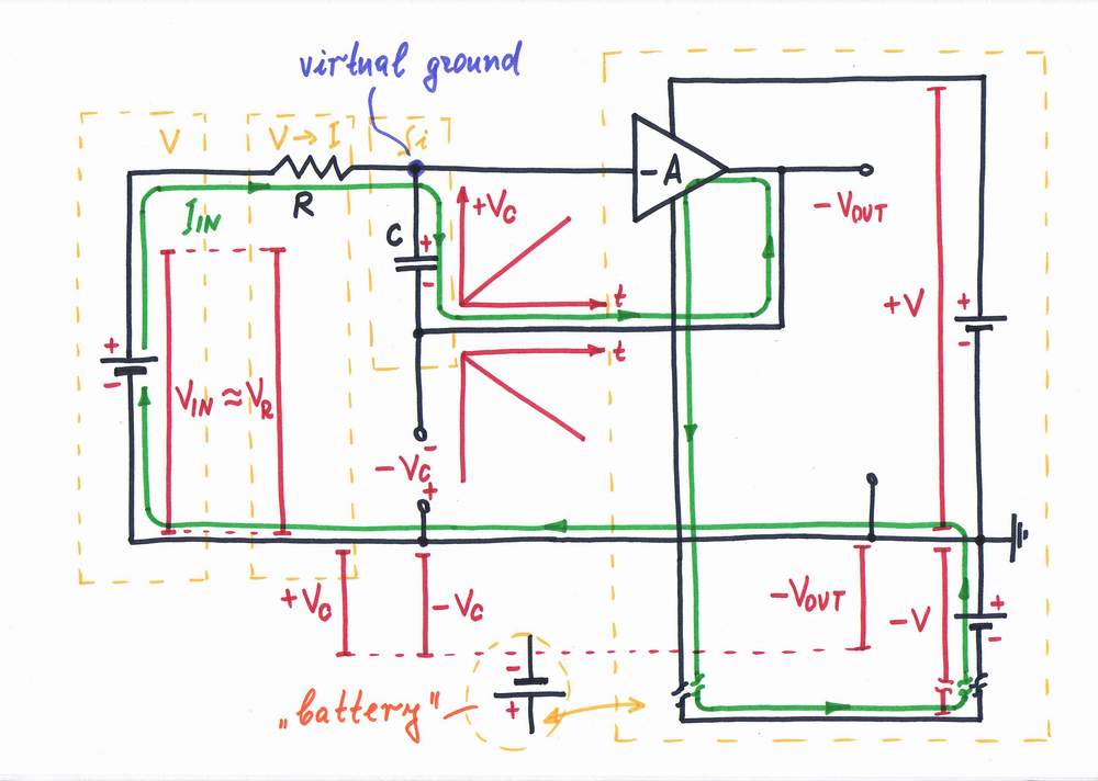
Again, let's redraw the circuit diagram in a more suitable form, in order to show this phenomenon.
< prev step - 0 - 1 - 2 - 3 - 4 - 5 - next step >
Finally, we have only to replace the "manual" op-amp with a real one. Now the op-amp doses the voltage of the power supply thus producing a compensating voltage -Vc. In other words, the combination of an op-amp and a steady battery acts as a varying battery BS.
The op-amp "observes" the potential of the point A (the difference between the two voltages) and changes instantly its output voltage so that the point A stays always at zero volts (acts as a virtual ground). Doing that, the op-amp compensates the "harmful" voltage drop across the capacitor by copying and adding it to the voltage of the input source (the op-amp helps the input source).
Don't do it! Finally, remove all the "unnecessary" components of the picture (voltage bars, current loops, power supplies etc.) and you will get the classic circuit diagram of the op-amp integrator. It will be simple, small, easy remembering but... nonunderstandable! Even if you adorn this bare circuit diagram with all kinds of formulas, it will remain nonunderstandable! Now you may add it at any recipe book on electronics:). Make sure looking at Google search: Op-amp integrator.
Here, the basic idea is hidden...
Related internal links:
Current-to-voltage capacitive integrator,
Voltage-to-voltage capacitive integrator,
Analog electronics 2004 - Class 4,
How I revealed the secret of parallel negative feedback circuits.
Related external links:
circuit-fantasia > circuit stories > building circuits > Op-amp inverting RC integrator roll short