 Inventing Circuits on the Whiteboard...
Transimpedance Amplifier (Current-to-Voltage Converter)
Transimpedance amplifier... It sounds scientific. It looks mysterious. It seems ununderstandable. Maybe, there is some confusing in the fact that there isn't a resistor connected to the inverting input? Actually, this is just a simple circuit with parallel negative feedback - only a resistor and, of course, an op-amp. It is so simple but there aren't human-friendly explanations of the circuit:(
Reading the traditional formal explanations (see an example), we can learn what transimpedance amplifier is; however, we can't understand it! In order to understand really this humble circuit, we first need to know what the problem of the simple current-to-voltage converter is and then, how the op-amp solves this problem. Simply speaking, we just want to know why the op-amp is connected there. I will try to answer these questions in three logically connected stories by using different viewpoint at the circuit - understanding, building and (re)inventing.
In this story, I will reveal the secret of the legendary circuit by reinventing it. First, we will use the favorite inventive tools - analogies. Then, in order to feel what the electronic components (sources, op-amp etc.) do, we will perform their functions (i.e, we will use the so called empathy). I hope you have fun:)
Internal links:
1. How do we measure a current by using... a voltmeter?!?
2. "Inventing" a passive current-to-voltage converter
3. Remedy: Removing voltage by an "antivoltage"
4. Problem: Where to take an output from?
5. How the active current-to-voltage converter operates (+VIN)
6. How the active current-to-voltage converter operates (-VIN)
7. "Inventing" op-amp current-to-voltage converter (+VIN)
8. How the op-amp current-to-voltage converter operates (-VIN)
Color key
Links: this page, other my pages, external, multimedia, handmade.
Text: analogies, conclusions.
top < prev step - 1 - 2 - 3 - 4 - 5 - 6 - 7 - 8 - 9 - next step > end
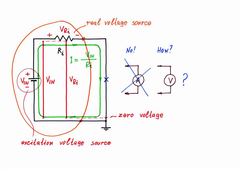
Imagine we have to measure the current flowing through a circuit. What kind of circuit? Let's for concreteness consider the possibly simplest electrical circuit consisting of a voltage source VIN and a resistor Ri. You might think of this circuit just as a shorted real voltage source (but yet, I hope that you have not got a 60A/h car battery:) or as a shorted simple current source with internal excitation voltage VIN and resistance Ri.
We suppose that the circuit obeys Ohm's law (IIN = VIN/Ri) and want to ascertain this speculation. Unfortunately, imagine we have not an ammeter; instead, we have only a voltmeter (saying "voltmeter" I mean a measuring device with extremely high input resistance, e.g. digital multimeter). Only, there isn't any voltage across the right part of the circuit. What do we do?
As we know from our routine, if something moves freely, there isn't any pressure. Mechanical analogy: freely moving car doesn't experience a pressure. Fluid analogy: imagine an old-fashioned vacuum cleaner sucks and blows air through a closed loop made from a corrugated hose. What is the pressure along the loop? Of course, it is zero everywhere in the hose.
Op-amp circuit builder (go to Stage 1)
How do we measure a current by using... a voltmeter?!?
top < prev step - 1 - 2 - 3 - 4 - 5 - 6 - 7 - 8 - 9 - next step > end
We also know that if something moving encounters an obstacle, a pressure appears. Mechanical analogy: if we try to stop a moving car with your body:), it exerts pressure to us. Fluid analogy: pinch the corrugated hose in the middle and you will see that a pressure appears across the bottleneck (the upper part lengthens while the lower shortens).
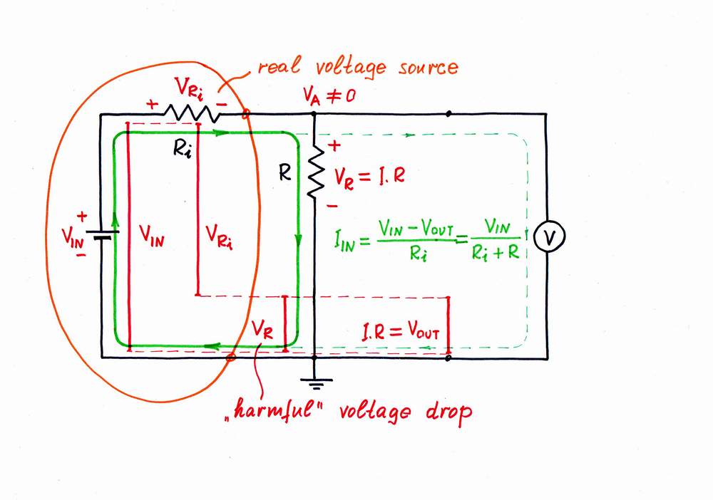
Well, let's apply this idea in the electricity domain. For this purpose, just break the circuit and connect a resistor R, in order to impede the current IIN. As a result, a voltage drop VR = I.R appears across the resistor R and we use this drop as an output voltage VOUT (the Norton's idea). Here, the resistor R acts as a simple passive current-to-voltage converter.
A problem. Only, a contradiction appears here: from one side, the voltage drop VR across the resistor R is useful for us (this is the output voltage needed!); from the other side, this voltage drop is harmful as it enervates the excitation voltage VIN. Now the voltage difference VIN - VR determines the current instead the voltage VIN. Measuring the current, we disturb it! As a result, the current IIN decreases. What do we do to solve this contradiction?
Another problem. Also, if the load (the voltmeter) is not so perfect (i.e., it has some resistance), some part of the current IIN will diverts through the voltmeter. As a result, both the current IIN and the voltage VIN decrease.
"Inventing" a passive current-to-voltage converter
Op-amp circuit builder (go to Stage 2 and select R2 from the library)
Current-to-voltage passive converter, Analog electronics 2004: Class 2
top < prev step - 1 - 2 - 3 - 4 - 5 - 6 - 7 - 8 - 9 - next step > end
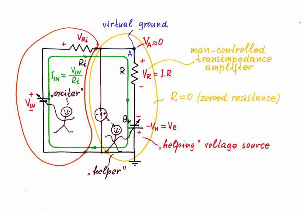
Remedy. What do we do in real life when a disturbance stands in our way? We remove it by an equivalent useful "antidisturbance". For this purpose, we usually use an additional power source, which "helps" the main source by compensating only the local losses. "Sunny" analogy: if the windows are dirty and we are lazy enough, we switch on additional lamps inside the room to "help" the sun (instead just to clean the windows:).
Implementation. Now, let's put this powerful idea into practice. Here, the voltage drop VR across the resistor R is harmful; so, following the recipe above, we have to remove it by an "antivoltage" -VR. In other words, we have to add so much voltage to the input (excitation) voltage source VIN, as much as it loses across the resistor R. The best way to understand what real electronic components do is just to do their work; so, I will do that donkeywork while you change the input voltage. For this purpose, I place an additional supplementary battery BH in series to the resistor R; then, I connect a zero indicator in point A and finally, adjust the battery voltage so that VH = -VR. As a result, the "harmful" voltage VR and the resistance R disappear; the point A becomes virtual ground. The real voltage source (the passive current source) is "fooled": it has the illusion that there isn't resistor connected; it "thinks" that its output is shorted.
How simple it is - add an adjustable battery in series with the resistor and make its voltage equal to the voltage drop across the resistor!
Remedy: Removing voltage by an "antivoltage"
How I revealed the secret of parallel negative feedback circuits
Analog electronics 2004: Class 9
Inventing parallel voltage-to-voltage active summer
Op-amp circuit builder (go to Stage 3 and select R2 from the library)
top < prev step - 1 - 2 - 3 - 4 - 5 - 6 - 7 - 8 - 9 - next step > end
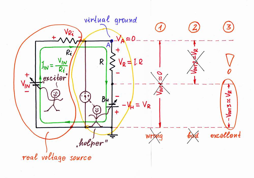
Now, we have to decide where to take the output (where to connect the load). Let's consider the possible solutions.
1. VOUT1 = VA = 0. It is naturally to try using the old circuit output (the voltage of point A versus the ground). But we have just destroyed this voltage (the point A has become virtual ground)! So, we can't use this voltage as an output:(
2. VOUT2 = VR. Then let's try using the voltage VR across the resistor R. Only, in order to connect a load to the "floating" resistor R, the load has to have a differential input. Moreover, if the load has some resistance, it will shunt the resistor thus affecting the current. What do we do then?
Recall to mind the cases from our routine when we prefer to estimate indirectly some quantity X. For this purpose, we first destroy the unknown quantity by an equal "anti-quantity" Y = X; then, we measure the "anti-quantity" Y, in order to know the magnitude of the initial quantity X. An example - classic weighing by using balance.
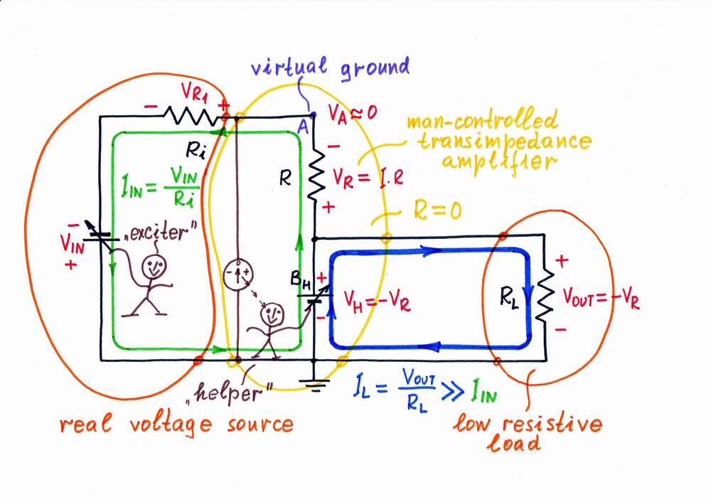
3. VOUT3 = -VH. Eureka! We will use the "copy" voltage -VH as an output instead the "original" voltage VR! What a great idea! First, the load will be connected to the common ground; second, it will consume energy from the "helping" source BH instead from the input source VIN!
Problem: Where to take an output from?
How I revealed the secret of parallel negative feedback circuits
top < prev step - 1 - 2 - 3 - 4 - 5 - 6 - 7 - 8 - 9 - next step > end
It's time to explore the circuit operation. In the beginning, imagine that there isn't input excitation voltage VIN.
Zero input voltage. As a result, there aren't any voltage drops and currents in the circuit; the needle of the zero indicator points to zero position.
Positive input voltage. If you increase the input voltage VIN, an input current IIN begins flowing through the resistor R. As a result, a voltage drop VR appears across the resistor R and the point A begins rising its potential VA (figuratively speaking, the input source "pulls" the point A up toward the positive voltage VIN). Only, I observe that the needle deflects to the right and immediately react by decreasing the compensating voltage VH. It "pulls" the point A down toward the negative voltage -VH until it manages to zero the potential VA (the virtual ground). Note that the two voltage sources are connected in series, in one and the same direction (- VIN +, - VH +) so that their voltages are added (let's assume that we traverse the loops clockwise). Regarding to the ground, they have opposite polarities.
Inventing parallel voltage-to-voltage active summer (go to Page 6-1)
Op-amp circuit builder (go to Stage 3 and select R2 from the library)
How the active current-to-voltage converter operates (+VIN)

top < prev step - 1 - 2 - 3 - 4 - 5 - 6 - 7 - 8 - 9 - next step > end
Negative input voltage. If you decrease the input voltage VIN under the ground, an input current IIN begins flowing through the resistor R in opposite direction. As a result, a voltage drop VR appears across the resistor R and the point A begins dropping its potential VA (now, the input source "pulls" the point A down toward the negative voltage -VIN). Only, I observe that the needle deflects to the left and immediately react by increasing the compensating voltage VH. Now, it "pulls" the point A up toward the positive voltage VIN until it manages to zero again the potential VA (virtual ground). The two voltage sources are connected in series again, in one and the same direction (+ VIN -, + VH -) so that their voltages are added. Regarding to the ground, they have again opposite polarities.
How the active current-to-voltage converter operates (-VIN)
top < prev step - 1 - 2 - 3 - 4 - 5 - 6 - 7 - 8 - 9 - next step > end
Only, I have got bored of doing this donkeywork; it is beneath my dignity to do it:) Well, I will try to make some electronic device do it; an op-amp seems to be a good choice. For this purpose, I connect the op-amp's output in the place of the helping voltage source and the op-amp's input to point A. As a result, the op-amp compensates the "harmful" voltage drop across the resistor by copying and adding the "copy" voltage to the voltage of the input source (the op-amp produces the compensating voltage VOA = -VR by dosing the voltage of the power supply). Thus, the op-amp "helps" the input source.
Positive input voltage. If you increase the input voltage VIN, an input current IIN begins flowing through the resistor R. As a result, a voltage drop VR appears across the resistor R and the point A begins rising its potential VA. (the input source "pulls" the point A up toward the positive voltage VIN). Only, the op-amp "observes" that and immediately reacts: it decreases its output voltage sucking the current IIN until it manages to zero the potential VA (the op-amp "pulls" the point A down toward the negative voltage -V, in order to establish a virtual ground). The op-amp does this magic by connecting a part of the voltage produced by the negative power supply -V in series with the input voltage VIN. As above, the two voltage sources are connected in series, in one and the same direction (- VIN +, - VH +) so that their voltages are added. Regarding to the ground, they have opposite polarities again.
"Inventing" an op-amp current-to-voltage converter (+VIN)

In a transimpedance amplifier, the op-amp acts just as a small battery, which adds so much voltage as it loses across the resistor R.
Inventing parallel voltage-to-voltage active summer (go to Page 6-6)
Op-amp circuit builder (go to Stage 4 and and select R2 from the library)
top < prev step - 1 - 2 - 3 - 4 - 5 - 6 - 7 - 8 - 9 - next step > end
Negative input voltage. If you decrease the input voltage VIN under the ground, an input current IIN begins flowing through the resistor R in opposite direction. As a result, a voltage drop VR appears across the resistor R and the point A begins dropping its potential VA (now, the input source "pulls" the point A down toward the negative voltage -VIN). Only, the op-amp "observes"' that and immediately reacts: it increases its output voltage "pushing out" the current IIN until manages to zero the potential VA (now, the op-amp "pulls" the point A up toward the positive voltage +V, in order to establish a virtual ground). The op-amp does this magic by connecting a part of the voltage produced by the positive power supply +V in series with the input voltage VIN. The two voltage sources are connected in series again, in one and the same direction (+ VIN -, + VH -) so that their voltages are added. Regarding to the ground, they have opposite polarities as above.
How the op-amp current-to-voltage converter operates (-VIN)

Power considerations
Only, if the op-amp current-to-voltage converter that we have created is so good, why do the popular multimeters not work that way? In order to measure current, they use the imperfect passive current-to-voltage converter instead the almost ideal op-amp current-to-voltage converter. Why?
If we look at the basic circuit implementing the "helping" idea, we will see that all the input current IIN flows through the "helping" voltage source BH. So, the source has to be able to endure such a current.
Accordingly, in the practical op-amp circuit, both the power source and the op-amp have to endure the input current measured. Imagine what this means, if we try, for example, to measure a current of 10A (a usual maximum current range in all purpose DVM). In this case, we have to use a car battery as a power supply:) and a power op-amp, which is able to dissipate 100W!
So, the active (op-amp) current-to-voltage converter is suitable only for low-current applications:(
top < prev step - 1 - 2 - 3 - 4 - 5 - 6 - 7 - 8 - 9 - next step > end
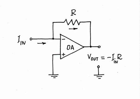
Warning: this is only a humor! Finally, imagine what you will do, if you are reputable author who write a book for a reputable publisher (I ask you persistently, don't do it!). You will remove all the "unnecessary" components of the picture (voltage bars, current loops, frivolous analogies, lengthy explanations etc.) and you will get the classic circuit diagram of transimpedance amplifier. It will be simple, small, easy remembering, convenient for teaching but... nonunderstandable! Even if you adorn this bare circuit diagram with all kinds of formulas, it will remain nonunderstandable!
Drawing this classic circuit diagram in such a formal and dull way, you deeply hide the basic idea behind the legendary circuit. Now, you may add it at any recipe book on electronics. Reading it, poor students will unsuccessfully try to grasp what the idea is. You may find tons of links pointing to such resources:
Google: transimpedance amplifier, current-to-voltage converter.
But yet, if you find some exception of this convention, please, let me know! I will be extremely glad to get in touch with the author.
Restoring the classical dull circuit diagram
Here, the basic idea is hidden...
circuit-fantasia > circuit stories > inventing circuits > transimpedance amplifier
Last updated April 7, 2007