To my students from Faculty of Computer Systems, spring 2006
 Inventing Circuits on the Whiteboard...
Constant Current Source (Ramp Generator)
I have already presented the philosophy of understanding and building constant current sources. Only, the best way of presenting these famous circuits to creatively thinking people is to reinvent (why not even invent?) them. Then, let's do that!
In order to "invent" a circuit, I suggest to use 4-step inventing "scenario". First, we derive the most common non-electrical basic ideas from our routine by scrutinizing various analogies (we will rely mainly on communicatiing vessels - my favorite water analogy). Second, following these ideas, we develop general (usually "man-controlled") electrical circuit. Third, according to these base circuit solutions and using various active electronic components (transistor, op-amp etc.), we "invent" the specific electronic circuit (s) enriched with voltage bars, current loops and other heuristic tools. Finally, we clean the circuit, in order to show what classic circuit we have actually "invented". We will apply this inventing procedure to all the stages of the constant current source creating:
|
|
|||||||||||||||||||||
As usual, I have coded the links below with a color key as follows: this page, other my pages , external, multimedia and handmade written resources. |
||||||||||||||||||||||
top < prev step - 1 - 2 - 3 - 4 - 5 - 6 - 7 - 8 - next step > end
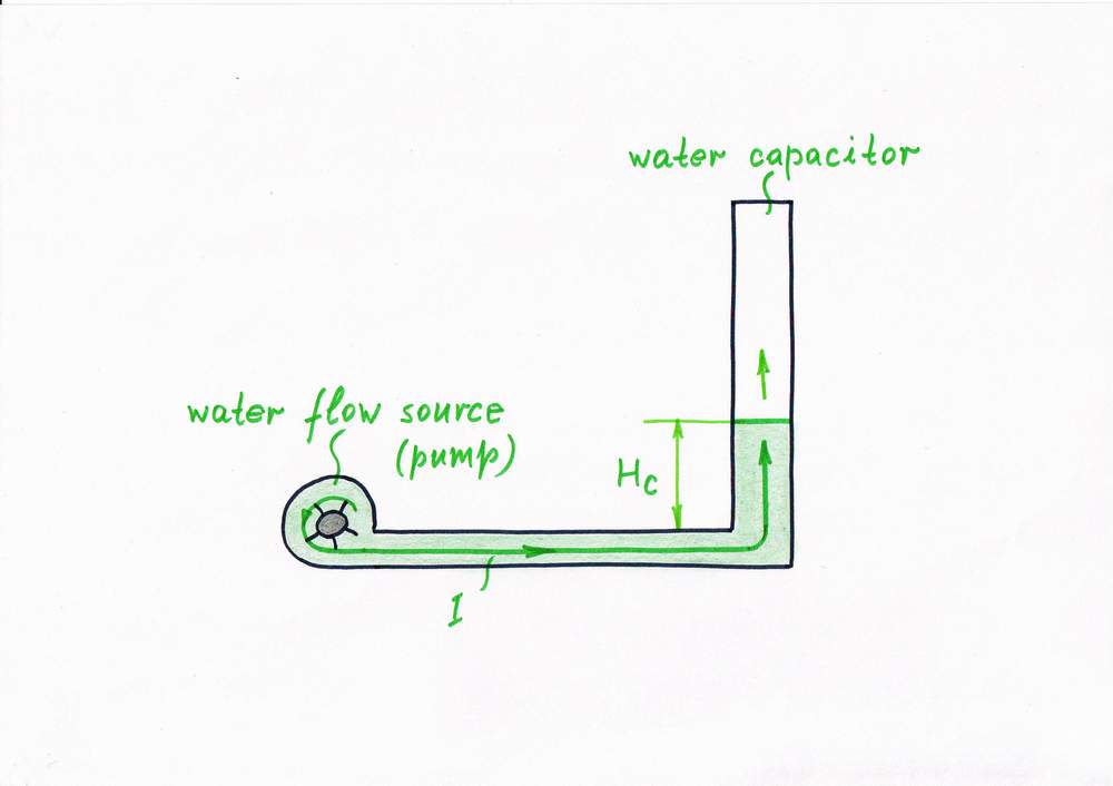
Let's begin with a simple hydraulic analogy: a water pump acting as a water constant flow source fills a cylindrical vessel (a "capacitor"). The flow source keeps a constant flow although the water level increases steadily (linearly) through time. But this is just a water clock, isn't it?
An example: A water tower acting as a water "capacitor"
Google search: water analogy
Idea 1: Keeping a constant current by using an ideal current source
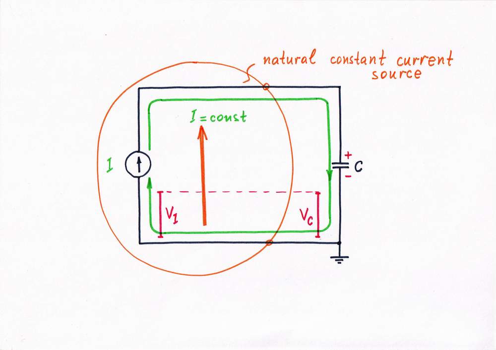
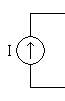
Now, let's build the corresponding electrical circuit: a constant current source I charges a capacitor C. Just like the hydraulic analogy, the current source keeps a constant current I although the voltage Vc increases steadily (linearly) through time. As a result, we have got a ramp generator.
How do we build an op-amp RC integrator (step 1)?
Google search: constant current source, ramp generator
top < prev step - 1 - 2 - 3 - 4 - 5 - 6 - 7 - 8 - next step > end
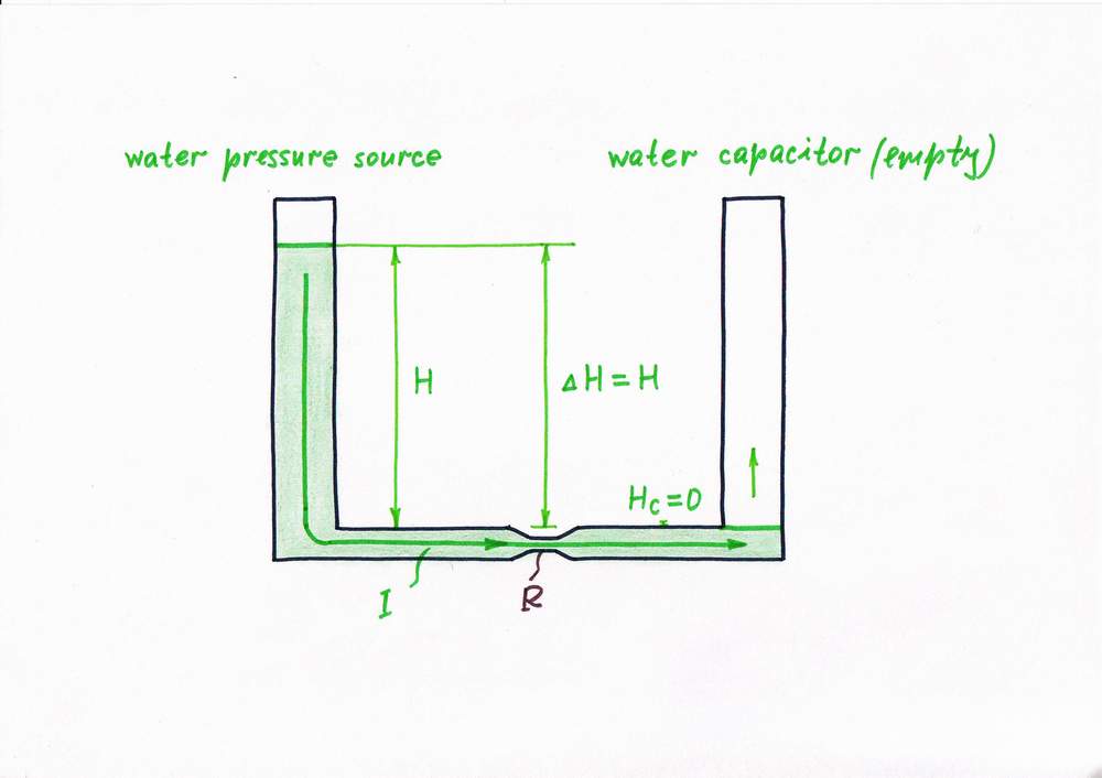
Only, suppose we have not so suitable constant flow source; instead, we have a water pressure source. It is just a cylindrical vessel filled of water (the higher the level, the stronger the water pressure at the bottom of the vessel). So, a natural question arises here: Can we convert this pressure source into a flow one?
Obviously, we can but we have to limit (dose) in some way the water flow rate, in order to get a steadily increasing water level in the right vessel. With this purpose, let's connect a valve (a fluid "resistor") between the water source and the water load. Thus we get the popular water circuit communicating vessels. Actually, the valve acts here as a pressure-to-flow converter; the whole combination of the constant pressure source and the pressure-to-flow converter acts as a constant flow source:
P-source + P-to-F converter = F-source
In the beginning, the right vessel (the water "capacitor") is empty; so, only the height H of the water pressure source (and the "resistance" R, of course) determines the flow rate I.
Voltage causes current - fluid analogies
Google search: communicating vessels
Idea 2: Keeping a constant current by using an ideal current load
In the electrical domain, there are not natural constant current sources (excepting inductor and Van der Graaf generator); but there are a lot of natural constant voltage sources (primary and secondary batteries). So, similarly a natural question arises here: Can we convert this voltage source into a current one?
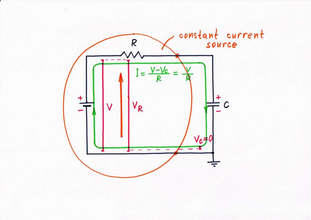
Again, we can but we have to limit (dose) in some way the current, in order to get a steadily increasing voltage across the capacitor. With this purpose, let's connect a resistor between the voltage source and the capacitor. Thus we get the simplest circuit of ramp generator. In this circuit, the humble resistor R acts as a voltage-to-current converter; the whole combination of the constant voltage source and the voltage-to-current converter acts as a constant current source:
V-source + V-to-I converter = I-source
In the beginning, the capacitor is empty; so, only the voltage V of the excitation voltage source (and the resistor R) determines the current I.
Paradox: This possibly simplest passive current source works in ideal load conditions (its output is shortened); so, it actually behaves as a perfect current source.
What is the idea behind a simple current source shortened?
top < prev step - 1 - 2 - 3 - 4 - 5 - 6 - 7 - 8 - next step > end
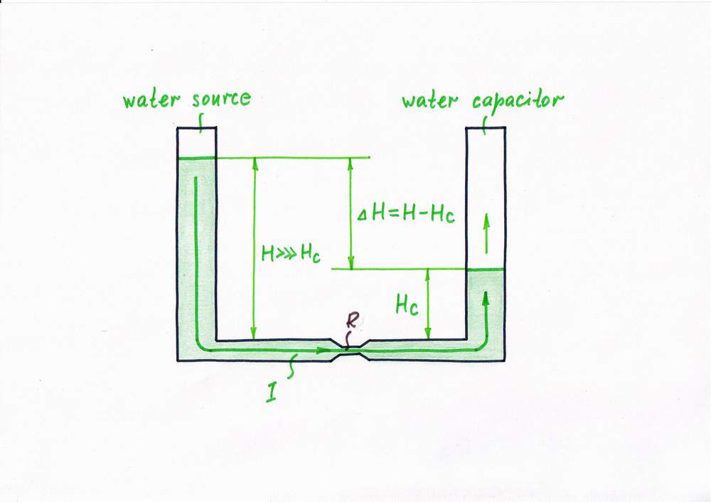
Problem. Unfortunately:), the water level Hc of the right vessel (the water "capacitor") increases steadily in the course of time. Now, the height difference H - Hc determines the flow rate I instead the height H of the water pressure source as above. It turns out that the water level Hc is harmful regarding the source as it enervates the excitation water level H. As a result, the flow decreases; our would-be water clock will operate inaccurately. What can we do, in order to decrease the error? Let's think.
Actually, both the height Hc and the constriction R are harmful quantities ((in regard to the source) as they impede the flow. Only, the height Hc is more harmful as it varies; so, we have to depreciate it.
Remedy 3. We can find out many examples in our routine where we have to depreciate something. E.g. what can a chief do, in order to depreciate an impeding team member (in a case when he can't give him the sack:)? He can increase the wage fund (the source) and appoint more team members (R)!
Similarly, in our water analogy, we can increase both the excitation height Hc and the constriction R. As a result, the flow remains the same but the influence of the height Hc decreases; thus we get a comparatively constant flow water source.
Idea 3: Keeping a constant current by depreciating the load
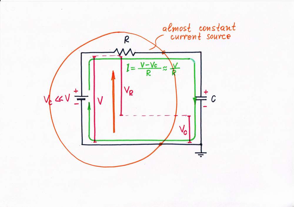
Problem. Similarly, the voltage drop Vc across the capacitor C increases steadily through time. Now, the voltage difference V - Vc determines the current I instead the excitation voltage V as above. Obviously, the voltage drop Vc across the capacitor is harmful as it enervates the excitation voltage V. As a result, the current decreases. The voltage drop Vc will change not linearly through time; so, we will get a sawtooth generator instead a ramp one. Let's think again using the reasonings obtained from the water analogy.
Apparantly, both the voltage drop VC and the resistance R are harmful quantities (in regard to the source) as they impede the current. Again, the voltage drop VC is more harmful as it varies; so, we have to depreciate it.
Remedy 3. Following the general idea derived from the water analogy, we increase both the excitation voltage V and the "resistance" R. As a result, the current remains the same but the influence of the voltage drop Hc decreases; thus we get a comparatively constant current source.
If we continue increasing these quantities up to infinity, we will get the classic ideal current source (well-known from any textbook on electricity). See also:
What is the idea behind a simple current source (real loaded)?
top < prev step - 1 - 2 - 3 - 4 - 5 - 6 - 7 - 8 - next step > end
Until now, our water circuit was passive (static): in the beginning, we set the quantities H and R; then, we just observe the operation passively without doing something. Now, let's become more active:)!
Remedy 4. It stands to reason that as soon as the water level Hc increases steadily thus decreasing the flow, we can change some of the other quantities in the opposite direction, in order to keep the constant flow.
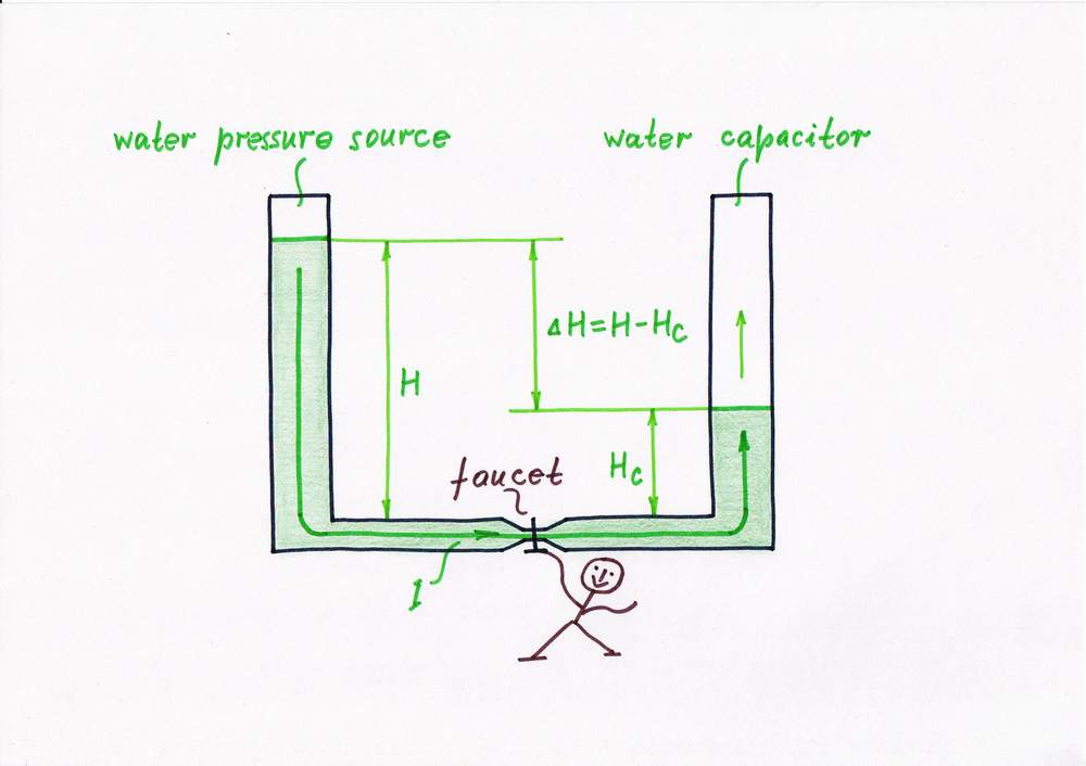
Let's begin with the impediment R replacing the valve with a faucet; then, we have to open steadily the faucet when the water level Hc increases. In this arrangement, the faucet will act as a kind of dynamic following valve.
Idea 4: Keeping a constant current by a following internal resistance
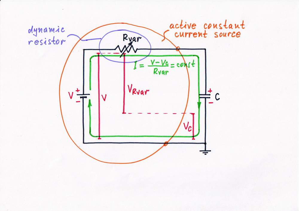
The problem of the simple current source is the same - the electrical quantities V and R stay constant while Vc changes. Then let's do them dynamic!
Remedy 4. In order to put into practice the first basic idea derived, replace the constant ohmic resistor R with a variable one Rvar (e.g. a rheostat). Then, decrease steadily its resistance, in order to compensate the current reduction. In this way, Rvar will act as a resistor with dynamic resistance.
Finally, assign this work to some active electronic component (BJ transistor):
What is the idea behind a simple bipolar transistor current source?
top < prev step - 1 - 2 - 3 - 4 - 5 - 6 - 7 - 8 - next step > end
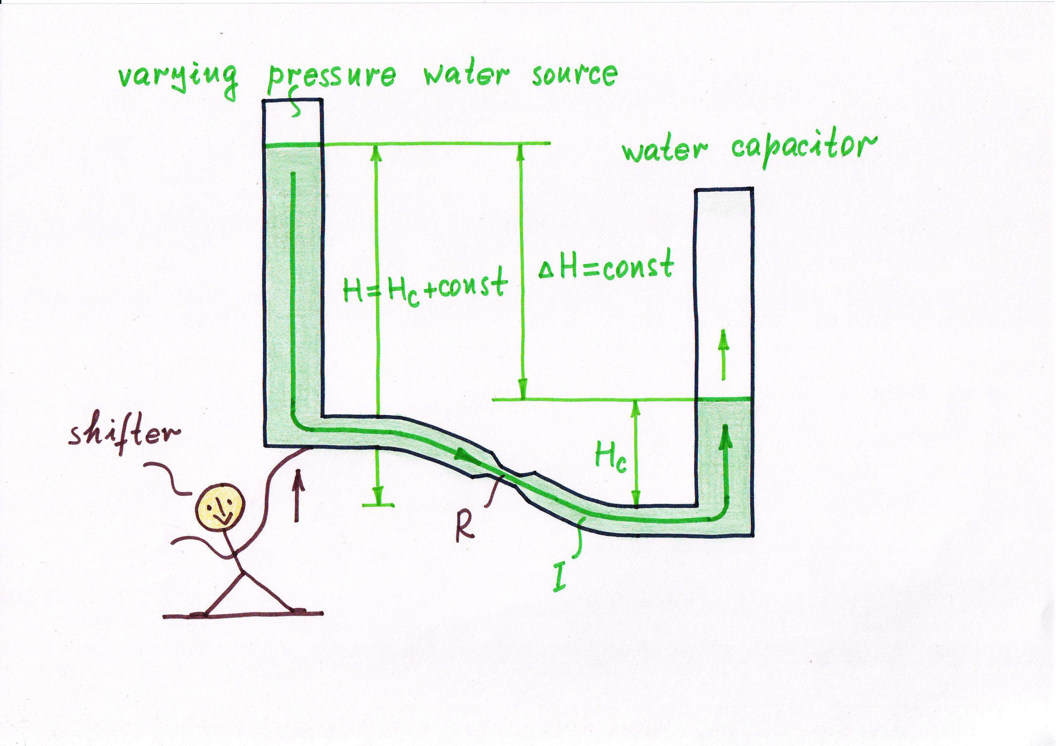
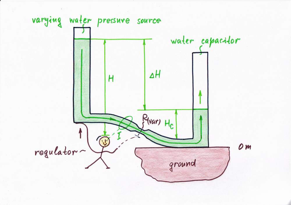
Remedy 5. The next powerful idea comes naturally to us - to change the excitation water level H, in order to compensate the variations of the "harmful" water level Hc. This means to lift steadily the water pressure source so as to follow the steadily increasing water level Hc. As a result, the height difference H - Hc and finally the flow will stay constant. The water pressure source acts as a kind of dynamic following source.
Congratulations! We have just invented the great idea of bootstrapping! They say that Baron Münchhausen has formulated it (he was using his own boot straps to pull himself out of the sea:). Note that bootstrapping describes different things in several domains.
Idea 5: Keeping a constant current by a following excitation voltage
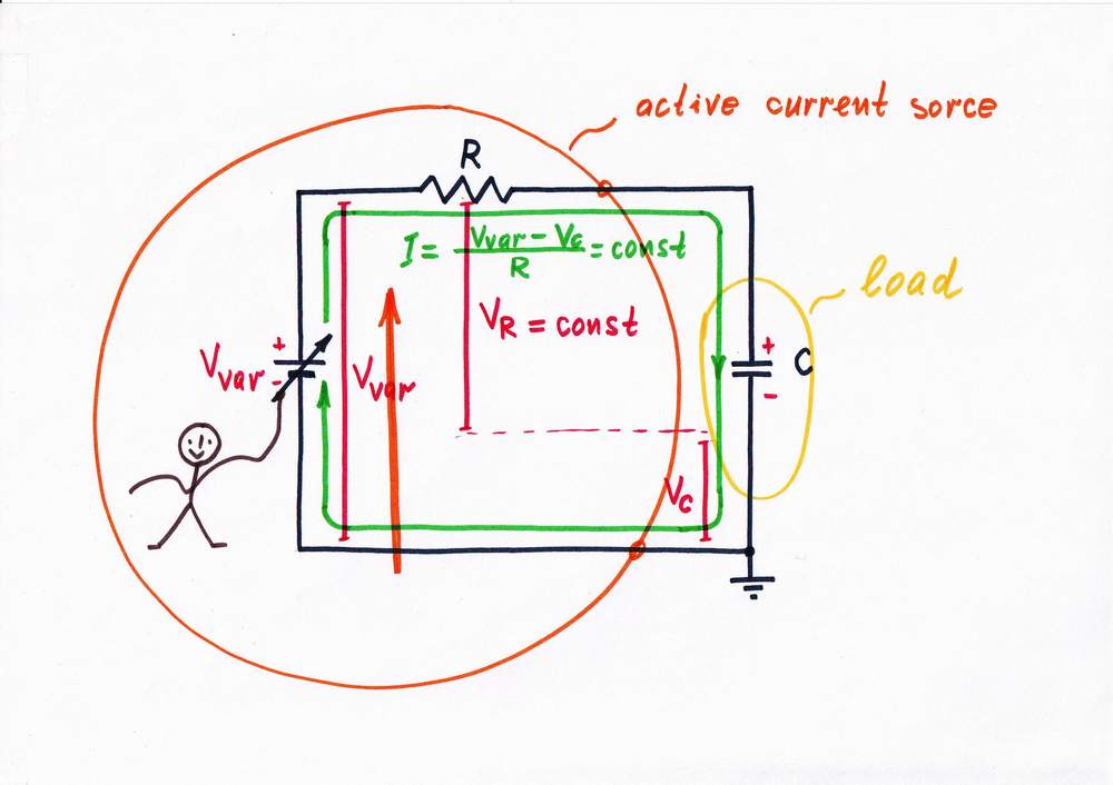
Remedy 5. Let's now apply the following idea (bootstrapping) in electronics, in order to "invent" the next attractive circuit. Well, change the excitation voltage Vvar (the former V) so as to follow the steadily increasing voltage drop Vc across the capacitor. As a result, the voltage difference Vvar-Vc and the current I will stay constant. The voltage source Vvar acts as a dynamic following voltage source.
Finally, let's assign this boring task to a transistor or to an op-amp:
Bootstrapped transistor current source with shifting diode
Bootstrapped transistor current source with shifting capacitor
top < prev step - 1 - 2 - 3 - 4 - 5 - 6 - 7 - 8 - next step > end
In the powerful idea above, we were lifting steadily the water pressure source so as to follow the steadily increasing water level Hc. In this arrangement, the left vessel (the water source) was movable while the right vessel (the water "capacitor") was fixed. But why don't we change the roles?
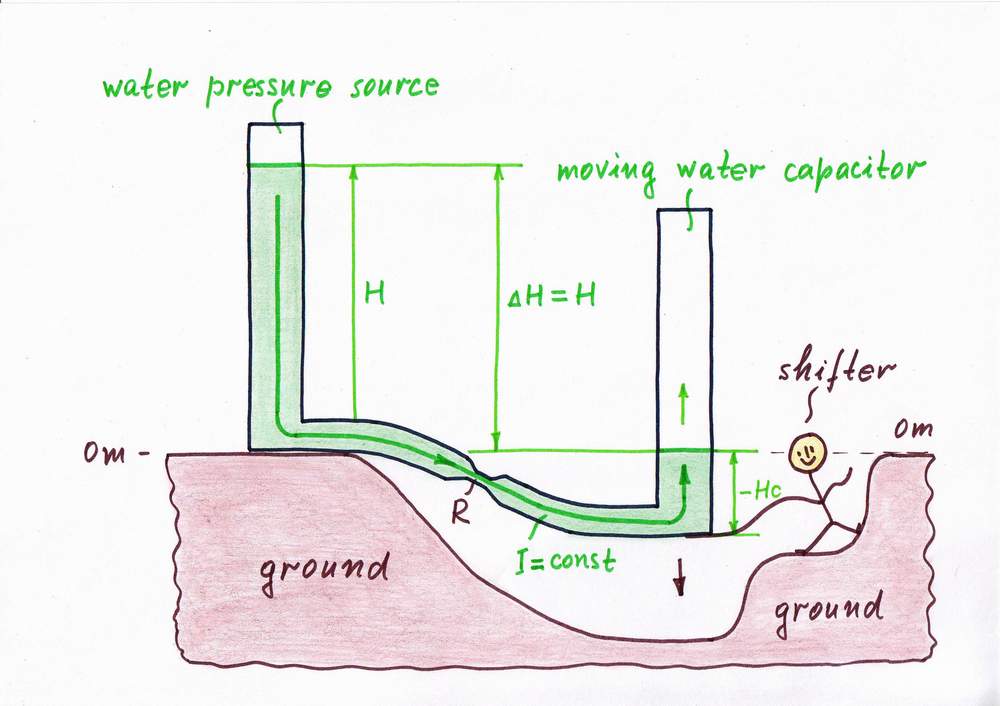
Remedy 6. Now, let the left vessel stay fixed while we drop steadily the right vessel under the ground (thus keeping zero water level). Wonderful! We have made a botomless vessel! The result obtained is the same as above: the height difference H - Hc stays again unchanged, the flow is constant and finally the combination of pressure source + constriction acts as a constant flow source as we want...
Lowering the water "capacitor" we remove the "harmful" water level Hc by an equivalent "antilevel" -Hc; so, we can name this idea removing a disturbance by an antidisturbance. From other viewpoint, we actually help the water pressure source (it is under the illusion that it fills an empty vessel). As above, here we add an additional water column to the initial source water one. So, we might also name the idea input source helping. But no matter the name, we can see this powerful idea in many situations of our routine.
Idea 6: Keeping a constant current by adding an additional voltage

Let's now "invent" the counterpart electrical circuit by applying the new powerful idea derived. Following this recipe, we have to remove the "harmful" voltage VC by an "antivoltage" -VC. That means to connect an additional supplementary battery BS and to adjust its voltage so that VS = -VC. As a result, the "harmful" voltage VC disappears and the point A becomes a virtual ground! The compound current source VIN-R is "fooled": it doesn't "understand" that there is a capacitor connected; it "thinks" that its output is shorted. The combination V + R acts as a constant current source.
The idea of removing a voltage by an antivoltage has an advantage versus the two ideas above since in many cases we can't change either resistance or voltage (e.g. imagine that V and R are located at long distance).
Again, an inverting op-amp can accurately do this routine work:
What is the idea behind an op-amp inverting current source?
How do we build an op-amp RC integrator (step 3)?
Building op-amp integrator (Step 3 & 4)
How I revealed the secret of parallel negative feedback circuits
top < prev step - 1 - 2 - 3 - 4 - 5 - 6 - 7 - 8 - next step > end
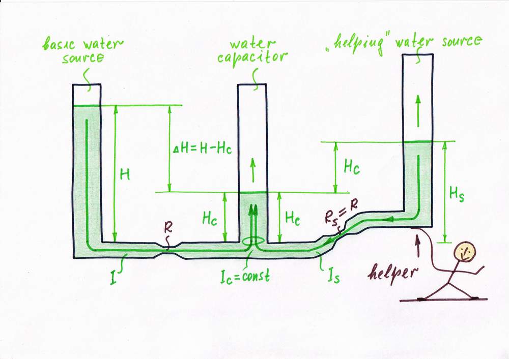
As we can see, the flow decreases because of the increasing "harmful" water level Hc of the right vessel. In the two previous cases, we have compensated these variations by adding an additional water column to the height difference H - Hc. Thus, we help indirectly the flow by increasing the effective water pressure. But why don't we help directly the water flow by adding an additional flow? Let's try it!
Remedy 7. Following this new idea, we connect another "helping" supplementary water source Hs through another constriction Rs to the water capacitor Hc. Then, we lift steadily the new water pressure source Hs so as to keep a constant height difference Hc between it and the water "capacitor". As a result, an additional flow Is will pour into the vessel; a constant flow Ic = I + Is will flow. What the brilliant idea!
If you are a driver, you can find another example of this trick in your car. When you (the excitation source) begin pressing the break pedal, the hydraulic system (the "helping" source) start "pressing" the same pedal, in order to help you.
Idea 7: Keeping a constant current by adding an additional current
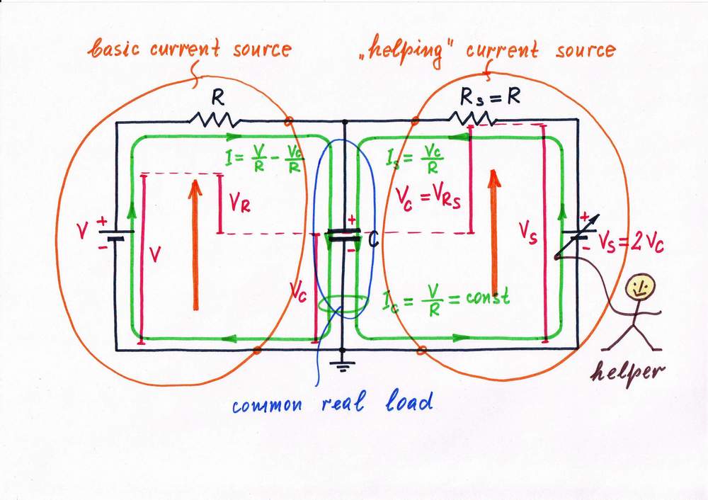
Similarly, in the simple current source, the current I decreases with VL/R because of the load voltage drop Vc. Above, we aided the exciting voltage source by an additional supplementary voltage source; thus, we helped indirectly the current by increasing the effective voltage V - Vc.
Remedy 7. Let's now use the last powerful basic idea - to help directly the current by adding an additional current, in order to "invent" the next famous circuit. According to this idea, we connect a "helping" voltage source Bs through another resistor Rs to the capacitor. In other words, we build another "helping" current source, which injects an additional current Is = Vc/R into the capacitor. Wonderful! We have reinvented the great Howland current source (a circuit with negative impedance but it is another game...)
Only, how to make an op-amp do this routine work? If you want to know, visit the page below:
What is the idea behind Howland op-amp current source?
top < prev step - 1 - 2 - 3 - 4 - 5 - 6 - 7 - 8 - next step > end
In all the examples until now, we were keeping constant flow without interesting in its magnitude. In other words, we have not applied negative feedback so far.
Remedy 7. Of course, the best solution is to observe the flow while changing the height H or the conctriction R (i.e. to apply a negative feedback).
There are more water analogies. For example, when you open the faucet in the bathroom we look at the water stream and adjust the faucet, in order to get the desired flow. Also, we do the same when we hose the garden.
We can see also examples of air analogies in our routine. E. g. we monitor the air flow of an air condition while regulating it by the remote control.
Google search: air analogy
Idea 8: Keeping a constant current by negative feedback

In the electrical domain, we also were keeping constant current without using negative feedback. To be more precise, we have implicitly used negative feedback e.g. to create a copy of disturbance (an "antidisturbance"). But we were just compensating the disturbing quantity (voltage, resistance etc.) without interesting in current magnitude.
In electricity, similarly to the water analogy, the best solution is to monitor the current I while change the resistance R or voltage V. So, in order to "invent" new constant current source, let's break the circuit and connect a constant resistor RI acting as a current-to-voltage converter (we prefer to measure voltage than current, why?). Then, using a reference voltage VREF and a zero indicator, let's keep a constant voltage VRI across the resistor RI. As a result, we get a stable current I = VREF/RI. If we assign this work to a transistor, an op-amp, a voltage regulator etc., we will get various circuits of constant current sources.
Analog electronics 2004: Class 7, Class 8, Sensor Bridge with Current Bias
top < prev step - 1 - 2 - 3 - 4 - 5 - 6 - 7 - 8 - next step > end
Place here your text explanations about various analogies related to this phenomenon.
Your Idea 9: Keeping a constant current by .............................
Place here your text explanations about your circuit of a constant current source.
Conclusions
In this story on the whiteboard, we have reinvented the six possible basic circuit solutions of the famous constant current source. For this purpose, we have applied one and the same 4-step inventing "scenario" (basic idea > general electric circuit > enriched electronic circuit > classic electronic circuit) to the six basic stages (depreciating the load > following resistance > following excitation voltage > adding a voltage > adding a current > applying a negative feedback) of the constant current source creating. In this way, we have revealed the evolution of these famous circuits.
circuit-fantasia > circuit stories > inventing circuits > constant current source
Last updated May 19, 2007