home - list of papers - Five Days in Stockholm
![]() 6th
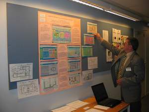
European Workshop on Microelectronics Education' 2006, Stockholm, Sweden, June 8-9
6th
European Workshop on Microelectronics Education' 2006, Stockholm, Sweden, June 8-9
Cyril Svetoslavov Mechkov
Department of Computer Systems, Technical University of Sofia,
e-mail: cyril@circuit-fantasia.com, site: http://www.circuit-fantasia.com

Abstract: In this paper, a new educational technology for teaching the fundamentals of analog electronics is proposed. Opposite to the traditional approach, it relies mainly on human imagination, intuition and emotions. In the proposed heuristic course, circuits are not analyzed as ready-made circuit solutions. Instead, the basic ideas behind the circuits are revealed first. Then, they are built systematically, step-by-step, each new circuit based on the previous ones. The heuristic approach is implemented as a set of interactive multimedia products where, in order to visualize the circuit operation, a set of innovative heuristic graphical tools is developed: voltage bars and diagrams, current loops, superimposed IV-curves etc.
Note: I have created this informal version, in order to give you full access to the web resources related (see also the more formal pdf and doc versions). The links are coded with a color key as follows: this page, my pages , external, multimedia and handmade drawn resources.
1. INTRODUCTION.
1.1. THE TRADITIONAL APPROACH. As a rule, classic electronics courses [1] follow a traditional "scenario": first, electronic circuits are presented in their complete, final and perfect form; then, they are accurately analyzed by using classical formal methods. Unfortunately, this approach does not reveal the nature of circuit phenomena as mathematical models hide structure, causality and structure-function relations.
We teachers have not to forget that students are not computers. First of all, they are human beings possessing fantasy, imagination and enthusiasm. So, in order to really understand how abstract electronic circuits work, they need "human" qualitative tools before formal methods to be applied.
 1.2. THE HEURISTIC APPROACH. My teaching heuristic philosophy [2] is simple:
1. Electronic circuits are based on clear and simple basic ideas, which may be derived from our routine.
2. In order to really understand electronic circuits, we human beings have first to reveal these basic ideas.
3. In order to successfully present circuits to students, we teachers have to build them according to the basic ideas revealed.
4. In order to make students think creatively, we teachers have to (re)invent circuits according to the basic ideas behind them.
Only after that, we have to apply formal methods, in order to determine circuit parameters.
2. TECHNOLOGY. Maybe, the best way to show how to put the heuristic approach into practice is to tell you how I deal with circuits.
2.1. UNDERSTANDING CIRCUITS. When I decide to really understand a new circuit I begin by breaking it up into smaller parts. For this purpose, I try to recognize separate groups of electronic components forming familiar simpler circuit building blocks (I have accumulated before some blocks in a circuit collection). Then, I try to discern familiar basic circuit ideas (I have also accumulated before some basic ideas in a principle collection).
 If familiar basic ideas do not exist, I begin looking for new ones. First, I browse through the other well-known circuits looking for similar concrete ideas. If I do not manage to find such "electrical" ideas, I begin looking for new "non-electrical" basic ideas in my routine. For this purpose, I look for everyday situations (analogies) in which a human being has a similar behavior.
Then I put myself mentally in device's place (i.e. I use empathy). For example, I replace real transistors and op-amps with man-controlled ones and begin performing their functions. Thus I get a taste of what the device feels and a picture of its behavior revealing cause and effect relations in its operation. I stir into action the circuit by stimulating mentally it and imagining how it reacts to this intervention. I do that mostly using my imagination rather than my reasoning, visualizing in my mind's eye how potentials rise and drop, currents flow from high to low potential point, resistors "shorten" and "lengthen", etc.
2.2. PRESENTING CIRCUITS. After I have restored the evolution of electronic circuits, I begin presenting them to students in their logical succession. First, I pose the problem that the circuit considered has to solve. Then I show the basic idea, on which the circuit is grounded on and draw the corresponding block diagram. Further, I build the circuit step-by-step. For this purpose, I use more elementary building blocks from the circuit collection connecting them accordingly to the block diagram (i.e. I replace the general blocks with concrete electrical blocks).
Then, I explore the circuit operation. In order students to penetrate into circuit operation, I perform step-by-step controlled experiments: imaginary experiments on the whiteboard in the classroom, animated experiments on the web and real experiments in the laboratory. In these arrangements, I replace the active electronic components (transistors, op-amps etc.) with man-controlled ones and begin performing their functions.
 In order to visualize the circuit operation (i.e. the invisible electrical attributes voltage and current), I have developed a set of heuristic graphical tools. Voltage bars present voltages and voltage drops by corresponding height (length) of a bar, voltage diagrams show the voltage allocation over the resistive film inside resistor, current loops present currents by corresponding contour thickness, superimposed IV-curves display working points etc. These graphical tools are colored, sounded, step-by-step controlled (animated) and illustrated by explanatory balloons and links.
In the laboratory, I carry on interactive computerized experiments where these "live" graphical representations on the screen are controlled by the real circuits investigated (see Ohm's experiment). In other experiments, live analogies (graphical representations of everyday situations on the screen) are controlled by the real circuits.
2.3. INVENTING CIRCUITS. I use it mostly to present circuits to creatively thinking students. In the beginning, applying a few inventive techniques, my students and I "invent" the simplest possible circuit building blocks. For this purpose, we assign consecutively the basic electrical attributes in the elementary Ohm's circuit as a circuit input and output (i.e. we change the causality between voltage and current), combine the elementary blocks reinvented into more complicated compound blocks etc. Only, a problem (contradiction) arises in the imperfect passive circuit and we begin trying to find a remedy. Usually, we begin looking around for analogies where a similar phenomenon appears (in the process of reinventing we give temporarily a more meaningful and live names of the phenomena). Gathering enough examples, we generalize them into a basic principle and a functional block diagram. Then, according to the general idea, we build initially a "man-controlled" electrical circuit and explore it step-by-step. Finally, we replace the "man-controlled" active components with real ones (transistors, op-amps etc.) thus getting a classical electronic circuit (see for example How do We Invent Constant Current Source? that I have dedicated to my students from Faculty of Computer Systems, spring 2006).
3. IMPLEMENTATION. Following the heuristic technology above I have gradually managed to build my own course as an alternative to the classical courses in the area of analog electronics. I have been applying this course in the class and laboratory exercises since 1987. Lately, I decided to support the class exercises of my students by a supplementary web-based circuit-building analog electronics course [3] located at circuit-fantasia.com.
3.1. CIRCUIT-BUILDING COURSE ON ANALOG ELECTRONICS. 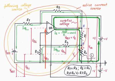 At the beginning of the course, my students and I derive the most elementary passive resistive analog devices with current (unit 1) and voltage (unit 2) output. Then, we use them to build more complicated compound resistive circuits with voltage input/output (unit 3) and also some classic time dependant circuits containing reactive elements (unit 4). After, we add electronic components to the passive circuits thus getting basic diode (unit 5) and transistor (unit 6) circuits. Next, we apply the powerful negative feedback principle to the transistor circuits thus getting classic transistor amplifying circuits (unit 7). Similarly, applying a feedback to the op-amp amplifying circuits, we get basic op-amp amplifiers with negative feedback (unit 8); then we convert the imperfect passive circuits from the beginning into almost ideal op-amp circuits (unit 9).
3.2. CIRCUIT STORIES ON THE WHITEBOARD. Lately, I have gradually realized that I spend a lot of time developing the interactive multimedia movies; I am afraid that I will not manage to implement all the ideas, which inhabit my mind. That is why, I have finally decided to begin visualizing them on a classic whiteboard; then snapping and placing them on the web. No Flash, no animations, no software tricks; only handmade pictures made by using colored fiber pens.
In these stories, I show three viewpoints at the circuits on the whiteboard: how to understand circuits (intended mainly to students and hobbyists), how to build circuits (to teachers) and how to invent circuits (to inventors and teachers). In the master index, web visitors are free to choose the favorite viewpoint at the circuit considered (see How do we Understand, Build or Invent a Constant Current Source?)
 3.3. CIRCUIT-BUILDING MULTIMEDIA TUTORIALS. A few years ago, I was fascinated by the power and interactivity of Macromedia Flash; then, I began creating with great enthusiasm variety of multimedia products.
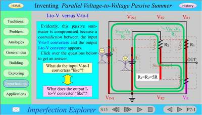
Reinventing op-amp voltage summer. I created the first circuit-building tutorial, in order to show how to present circuits by reinventing them. It consists of four units dedicated to the famous analog circuits voltage-to-current converter, current-to-voltage converter, passive voltage summer and op-amp voltage summer. In this chain of circuits, every next circuit is built by using the previous more elementary circuits. Every unit is based on one and the same 7-step circuit-building "scenario": problem, analogies, generalizing, building, exploring, imperfections and applications. Then I also developed a hierarchical menu in order to access the future collection of circuit building blocks invented (in order to view the basic ideas behind circuits, roll over the right hand side of the classification).
Build to understand circuits. In 2003 I was invited by Poptronics to develop a building tutorial for their web site. Then I was inspired to make an extremely interesting multimedia product and began working with fervor. Only, I had just managed to create Unit 1 when Poptronics ceased and this undertaking failed.
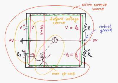
Op-amp circuit builder. I made this product, in order to reveal op-amp circuit evolution. For a long time, I have been noting that in classic 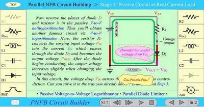 electronics courses, analog circuits are unnaturally divided into passive and active ones. First, students are persuaded how imperfect passive circuits are; then, students are given analogous active versions and they are convinced formally that these active circuits are almost ideal. However, nobody shows them what they really need in order to comprehend active circuit operation: how the passive and active versions relate and how passive circuits have been converted into active ones. Only, I had been feeling intuitively that such a relation existed and so I began looking for it. As a result, I have finally managed to reveal the secret of parallel negative feedback circuits (i.e. the so popular op-amp inverting circuits):
In these circuits, the op-amp acts as a supplementary voltage source; it aids the input voltage source by injecting as much energy (voltage) as it loses in the passive element - resistor, capacitor, diode etc.
In this interactive multimedia circuit "theatre" different electronic components play one and the same role on the circuit stage [4]. By applying a 4-step procedure over 40 popular analog electronic circuits are built by converting the passive versions into active ones (choose the circuit by clicking on the components located on the right and on the left of the scene).
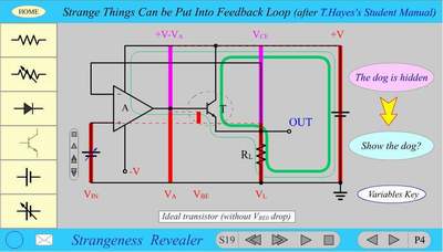 Strange things. I created this funny story in 2002 after Tom Hayes's Student Manual for the Art of Electronics [5]. The interactive multimedia tutorial reveals the unique feature of negative feedback systems to overcome all kinds of disturbances. It also shows how to build over a dozen op-amp circuits with a disturbance put into feedback loop (choose a disturbing element by clicking on the buttons located on the left of the scene; also, you may get an output before or after the disturbing element by clicking on the buttons located on the right of the scene).
4. WEEKLY UPDATED COLUMNS. In order to induce creativity, during 2004-2005 I was maintaining a few weekly updated columns: questions, paradoxes, contradictions, conflicts, principles, building schemes, circuit_building blocks.
5. CONCLUSIONS. The heuristic approach proposed is most appropriate for developing student and teacher's abilities for creative thinking. It stimulates the way of reasoning needed to create, synthesize and even invent new circuits. This approach may be successfully applied in other areas of engineering education.
REFERENCES.
[1] Floyd, T., Buchla, D., Fundamentals of analog circuits, Prentice-Hall, 1999.
[2] Mechkov C., Circuit-building electronics tutorial, Proceedings of The 12-th Int. Conference ELECTRONICS'2003.
[3] Mechkov C., Web-based circuit-building course on analog electronics, Proceedings of The 13-th Int. Conference ELECTRONICS'2004.
[4] Mechkov C., Parallel negative feedback circuit builder, Proceedings of The 12-th Int. Conference ELECTRONICS'2003.
[5] Hayes, T., Horowitz, P., Student Manual for the Art of Electronics, Cambridge University Press, 1999.
home - list of papers - Five Days in Stockholm
Last updated, June 23, 2006