 Understanding Circuits on the Whiteboard...
Negative Impedance Converter (VNIC)
 Negative impedance converter (NIC) is one of the most interesting, odd, strange and even "mystic" electronic circuits, which are still unexplained (I have not yet met some "human-friendly" explanations of this legendary circuit on the web or in the books). Reading the formal and dull explanations of existing sources dedicated to this circuit, we can learn what NIC is (for example, "a circuit introducing a shift of 180° between the voltage and the current"); however, we can't understand it!
In order to understand really this sophisticated circuit, we need something more. As human beings (not computers), we first need to know what the general idea behind negative resistance is (that is, what negative resistance is), then, how to obtain negative resistance and finally, how the op-amp does that work (or what the op-amp actually does in the circuit of NIC).
From many years, I have been thinking about the phenomenon of negative resistance and its circuit implementation as NIC. Finally, I have managed to grasp the general idea behind them; now, I would like to share my insights with you. In the story below, I have shown how we can reason to reveal the secret of this sophisticated circuit.
There are two kinds of NIC: voltage inversion (VNIC) and current inversion (INIC). In this story, we will reveal the secret of the voltage inversion NIC. If you want to know the secret of the dual current inversion negative impedance converter (INIC), visit Circuit Idea wikibook.
Reasoning
Graphical representation
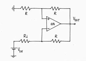
At first glance, the NIC circuit diagram looks apparently complex and unintelligible. However, if we scrutinize it, we will begin discerning well-known circuit solutions. Let's begin braking circuit into smaller subparts and try to guest what they do.
top < prev step - 1 - 2 - 3 - 4 - next step > end
Real voltage source. First, look at the left bottom side of the picture. What is the combination of the two components VIN and Ri? It represents a real voltage source acting as an input generator.
Voltage divider. Then, look at the top side of the picture. What is the combination of the two resistors with equal R? They constitute a voltage divider with K = 0.5. Detach temporarily it from the rest part of the circuit.
Transimpedance amplifier. Finally, look at the right bottom side of the picture. What are the op-amp and the resistor R connected between the op-amp output and the inverting input? A tip: temporarily ignore the upper voltage divider and suppose that the non-inverting input is grounded.
Eureka! But this is the familiar op-amp current-to-voltage converter (transimpedance amplifier). What does the op-amp do in this circuit? Walking through the loop VIN - VRi - VR + VOA we can see that a voltage drop VR = I.R loses across the resistor R; however, the op-amp adds the same voltage into the loop. As a result, the op-amp compensates perfectly the voltage drop across the resistor R; both the "harmful" voltage drop VR and the resistance R disappear (the real voltage source "has the feeling" that it is shorted). Aha, the main task of the op-amp here (and why not, in all the op-amp inverting circuits?) is just to zero the resistance R! How simply it is!
Actually, the op-amp acts as an additional supplementary voltage source, which "helps exactly" the excitation voltage source VIN in its efforts to create the current IIN - note that the two voltage sources are connected in series, in one and the same direction (- +, - +) so that their voltages are added.
Reinventing transimpedance amplifier
How I revealed the secret of parallel negative feedback circuits
Wikipedia: Transimpedance amplifier
Braking down the circuit of VNIC

What does the op-amp do in a transimpedance amplifier?
The op-amp continuously compares its own output voltage VOA with the voltage drop VR across the resistor R by subtracting the two voltages. It "observes" the result of the comparison - the voltage VA = VR - VOA of point A (the so-called virtual ground) and keeps it almost zero by adjusting the output voltage VOA = -VR = -I.R.
Current-to-voltage passive converter, Reinventing op-amp inverting summer
Op-amp circuit builder (click the resistor on the right hand side)
top < prev step - 1 - 2 - 3 - 4 - next step > end
It's time to see what the voltage divider does in this odd circuit. Connect it and see what the op-amp will do.
What does the op-amp do in NIC?
The op-amp continuously compares 1/2 of its own output voltage VOA with the voltage drop VR across the lower resistor R by subtracting the two voltages. It "observes" the result of the comparison - the voltage difference between the two inputs and keeps it almost zero by adjusting the output voltage VOA = -2VR = -2I.R.
Aha! Now, the op-amp is "misled" - it has to generate two times higher voltage VOA = -2VR = -2I.R, in order to keep zero voltage between its two inputs. Half the voltage (VR) compensates the voltage drop VR; the rest half (VR) is added to the excitation voltage source VIN. So, the voltage divider (with K = 0.5) connected to the non-inverting input makes the op-amp "over-compensate" twice the voltage drop VR. Let's make a conclusion.
NIC is just an "over-compensating" transimpedance amplifier.
A heuristic approach to teaching negative resistance phenomenon
Wikipedia: My viewpoint at transimpedance amplifier,
What is the basic idea behind a negative impedance converter (NIC)?
Reassembling the circuit of VNIC

top < prev step - 1 - 2 - 3 - 4 - next step > end
Once we revealed what the op-amp does in the circuit of NIC, we can generalize the "over-helping" idea in a form of an equivalent electrical circuit.
NIC components
An internal resistor. Obviously, the "ordinary" resistor R acts as a passive current-to-voltage converter, which output voltage drives the "helping" voltage source BH. What a paradox! In order to get a negative resistor, they have connected internally an ordinary resistor! Well, we can make the first general conclusion: NIC (a negative resistor with resistance -R) contains internal resistor with resistance R.
An internal doubling voltage source. Evidently, the op-amp acts as an "over-helping" voltage source that doubles the voltage across the resistor R (voltage amplifier with K = 2). So, we can make the second general conclusion: NIC contains also an internal doubling voltage source (voltage amplifier with k = 2).
Wikipedia: What is the basic idea behind the negative impedance converter?
VNIC presented by an equivalent electrical circuit

VNIC = "ordinary" resistor + inverting voltage amplifier
top < prev step - 1 - 2 - 3 - 4 - next step > end
So far, we have managed to reveal the function of each component in the op-amp circuit of NIC. What is more, we have generalized it in a simple equivalent electrical circuit. But yet, can we finally answer in the possibly simplest way to the question "What is NIC?" Let's try.
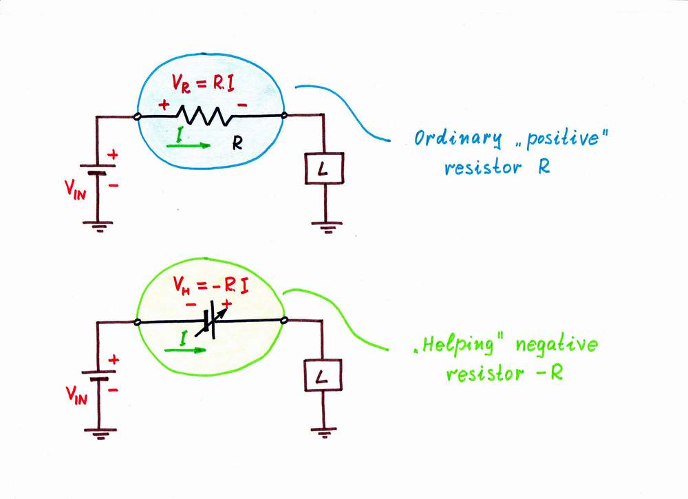
Actually, NIC is an op-amp circuit implementation of an "over-helping" negative resistor. So, we have first to answer the question "What is negative resistor?" For this purpose, let's compare the two kinds of resistors.
Let's a current I passes through a "positive" resistor R and through a negative resistor -R. As a result, a voltage drop VR = R.I appears across the resistor R and the same voltage VH = VR = R.I appears across the negative resistor -R. Only, the resistor R sucks a voltage VR = R.I from the circuit (it is a voltage drop) while the negative resistor -R adds a voltage VR = R.I into the circuit. So, a resistor acts as a current-to-voltage drop converter while a negative resistor acts as a current-to-voltage converter. The element named "resistor" is really a resistor while the "negative resistor" is actually a voltage source, whose voltage is proportional to the current passing through it. Then, let's make the final conclusion.
NIC is just an additional voltage source, which produces a voltage proportional to the current passing through the source; this voltage is added to the input voltage.
Wikipedia: What is the basic idea behind the negative impedance converter?
VNIC presented as an "over-helping" negative resistor
VNIC = "helping" current controlled voltage source
Circuit Idea wikibook:
Revealing the Mystery of Negative Impedance Converters
Investigating the Linear Mode of Negative Impedance Converters with Voltage Inversion
Investigating the Linear Mode of Negative Impedance Converters with Current Inversion
Investigating the Bistable Mode of Negative Impedance Converters with Current Inversion
circuit-fantasia > circuit stories > understanding circuits > VNIC
Last updated August 28, 2012